element14 Community
element14 Community
    Register Log In
  • Site
  • Search
  • Log In Register
  • Community Hub
    Community Hub
    • What's New on element14
    • Feedback and Support
    • Benefits of Membership
    • Personal Blogs
    • Members Area
    • Achievement Levels
  • Learn
    Learn
    • Ask an Expert
    • eBooks
    • element14 presents
    • Learning Center
    • Tech Spotlight
    • STEM Academy
    • Webinars, Training and Events
    • Learning Groups
  • Technologies
    Technologies
    • 3D Printing
    • FPGA
    • Industrial Automation
    • Internet of Things
    • Power & Energy
    • Sensors
    • Technology Groups
  • Challenges & Projects
    Challenges & Projects
    • Design Challenges
    • element14 presents Projects
    • Project14
    • Arduino Projects
    • Raspberry Pi Projects
    • Project Groups
  • Products
    Products
    • Arduino
    • Avnet Boards Community
    • Dev Tools
    • Manufacturers
    • Multicomp Pro
    • Product Groups
    • Raspberry Pi
    • RoadTests & Reviews
  • About Us
  • Store
    Store
    • Visit Your Store
    • Choose another store...
      • Europe
      •  Austria (German)
      •  Belgium (Dutch, French)
      •  Bulgaria (Bulgarian)
      •  Czech Republic (Czech)
      •  Denmark (Danish)
      •  Estonia (Estonian)
      •  Finland (Finnish)
      •  France (French)
      •  Germany (German)
      •  Hungary (Hungarian)
      •  Ireland
      •  Israel
      •  Italy (Italian)
      •  Latvia (Latvian)
      •  
      •  Lithuania (Lithuanian)
      •  Netherlands (Dutch)
      •  Norway (Norwegian)
      •  Poland (Polish)
      •  Portugal (Portuguese)
      •  Romania (Romanian)
      •  Russia (Russian)
      •  Slovakia (Slovak)
      •  Slovenia (Slovenian)
      •  Spain (Spanish)
      •  Sweden (Swedish)
      •  Switzerland(German, French)
      •  Turkey (Turkish)
      •  United Kingdom
      • Asia Pacific
      •  Australia
      •  China
      •  Hong Kong
      •  India
      •  Korea (Korean)
      •  Malaysia
      •  New Zealand
      •  Philippines
      •  Singapore
      •  Taiwan
      •  Thailand (Thai)
      • Americas
      •  Brazil (Portuguese)
      •  Canada
      •  Mexico (Spanish)
      •  United States
      Can't find the country/region you're looking for? Visit our export site or find a local distributor.
  • Translate
  • Profile
  • Settings
Design Challenges
  • Challenges & Projects
  • More
Design Challenges
Forum IST Flow Sens FS1 analog bridge circuit for cypress ble microcontroller
  • Forum
  • Documents
  • Polls
  • Files
  • Mentions
  • Sub-Groups
  • Tags
  • More
  • Cancel
  • New
Actions
  • Share
  • More
  • Cancel
Forum Thread Details
  • Replies 8 replies
  • Subscribers 8 subscribers
  • Views 1376 views
  • Users 0 members are here
Related

IST Flow Sens FS1 analog bridge circuit for cypress ble microcontroller

anthonythet
anthonythet over 8 years ago

Hi,

I am Anthony working as an Embedded system engineer for an electronic design house.

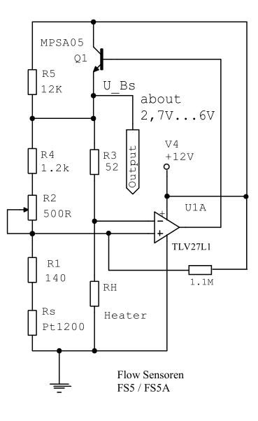
Currently, I need to do hardware design for an application in which we use IST FS1 sensor for measuring air flow rate from cypress ble microcontroller.

I just googled about this sensor and I got some application bridge circuit for this sensor but they are for Arduino (for 5V range).

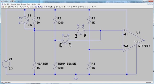
But what I need to interface is with ble microcontroller which can measure only 0 to 3.3V range.

Can I get application circuit for that sensor for cypress ble microcontroller?

I really need your help. Thanks.

  • Sign in to reply
  • Cancel

Top Replies

  • michaelkellett
    michaelkellett over 8 years ago +3
    Hello Anthony, If you are working for a design house is there not someone there who can help you a bit ? So far you haven't provided enough information to enable me (or anyone else) to help you much. The…
  • clem57
    clem57 over 8 years ago +1
    http://www.farnell.com/datasheets/318594.pdf?_ga=1.205053200.1055332836.1476990943 show voltage range is 2V to 5V...
  • michaelkellett
    michaelkellett over 8 years ago in reply to anthonythet +1
    It would be possible, the simplest way (least thought) is to use a boost regulator to generate a 12V supply. You didn't answer my earlier questions and without that information is not possible to give…
Parents
  • michaelkellett
    michaelkellett over 8 years ago

    Hello Anthony,

    If you are working for a design house is there not someone there who can help you a bit ?

    So far you haven't provided enough information to enable me (or anyone else) to help you much.

    The IST data sheets are limited but adequate, they have some additional material on their website.

    If you intend to measure the airflow you need to specify the range of flow rates you wish to cover, are you prepared to have adjustable resistors in your circuit for calibration or will you use maths and calibration data in the processor.

    Is there anything special about the processor, system power etc.

    If this is  a commercial application you should be able to get some help from IST.


    MK

    • Cancel
    • Vote Up +3 Vote Down
    • Sign in to reply
    • Cancel
  • anthonythet
    anthonythet over 8 years ago in reply to michaelkellett

    Hello Michael,

    Thanks for your reply and advices.

    Actually, in the sensor application note, they give the bridge circuit to read analog data but the output range is 2 to 6V and the supply voltage is 12V.

    I want to know is there anyway to scale down the range to 0 3.3V and reduce the supply voltage?Thanks.image

    • Cancel
    • Vote Up 0 Vote Down
    • Sign in to reply
    • Cancel
  • michaelkellett
    michaelkellett over 8 years ago in reply to anthonythet

    It would be possible, the simplest way (least thought) is to use  a boost regulator to generate a 12V supply.

    You didn't answer my earlier questions and without that information is not possible to give good advice.


    1) Do you care how much power the sensor circuit uses

    2) What working range of flow do you want to measure

    3) How will you calibrate it (pot, maths etc)

    4) How accurate must it be.

    5) Are there any cost constraints


    MK

    • Cancel
    • Vote Up +1 Vote Down
    • Sign in to reply
    • Cancel
  • anthonythet
    anthonythet over 8 years ago in reply to michaelkellett

    Hi Michael,

    Thanks for your reply,

    1) It is the portable application but I need to use li-ion 400mAh(or a little higher charge) battery.

    2) the customer give me the flow rate (not flow velocity) 9litre/hr to 30litre/h.

    3) I don't want to put hardware calibration but I also don't know how to calibrate with software algorithm.(but if no way, I have to put the hardware calibration)

    4) this accuracy is not much important.

    5) there are no cost constraints

    • Cancel
    • Vote Up 0 Vote Down
    • Sign in to reply
    • Cancel
  • michaelkellett
    michaelkellett over 8 years ago in reply to anthonythet

    The FS1 sensor may well be unsuitable for your application.

    9l per hour represents a velocity of 9000/0.785 = 11464 cm/hr, through a 1cm diameter tube.

    This is only 0.032m/s.

    The graphs in the IST documents start at about 0.2m/s so you will be working at 1/10th of the minimum flow rate they document.


    Step1 - talk to IST - find out if they think their sensor is good for this and if they have any advice.


    If IST won't talk to you then build a test rig (you were going to do that anyway I hope) and test the sensor using IST's standard circuit.


    Once you know if the sensor can get near to doing what you want you can then think about optimizing the circuit it should be possible to get close to a power consumption of about 300mW for the sensor and analogue circuits = I'm sure you can work out if the battery life will be good enough.


    If you are an embedded system engineer you really out to be able to the maths for the calibration - but you aren't ready to bother yet - first you must make sure the sensor will do what you want.


    MK

    • Cancel
    • Vote Up 0 Vote Down
    • Sign in to reply
    • Cancel
Reply
  • michaelkellett
    michaelkellett over 8 years ago in reply to anthonythet

    The FS1 sensor may well be unsuitable for your application.

    9l per hour represents a velocity of 9000/0.785 = 11464 cm/hr, through a 1cm diameter tube.

    This is only 0.032m/s.

    The graphs in the IST documents start at about 0.2m/s so you will be working at 1/10th of the minimum flow rate they document.


    Step1 - talk to IST - find out if they think their sensor is good for this and if they have any advice.


    If IST won't talk to you then build a test rig (you were going to do that anyway I hope) and test the sensor using IST's standard circuit.


    Once you know if the sensor can get near to doing what you want you can then think about optimizing the circuit it should be possible to get close to a power consumption of about 300mW for the sensor and analogue circuits = I'm sure you can work out if the battery life will be good enough.


    If you are an embedded system engineer you really out to be able to the maths for the calibration - but you aren't ready to bother yet - first you must make sure the sensor will do what you want.


    MK

    • Cancel
    • Vote Up 0 Vote Down
    • Sign in to reply
    • Cancel
Children
  • jc2048
    jc2048 over 8 years ago in reply to michaelkellett

    One way to reduce the power consumption might be to put the processor inside the loop since it's all working so slowly.


    The heater has a maximum voltage of 3V. If that was driven by the processor with PWM, with the thermometer element read in a bridge and the processor doing the servo-ing, the consumption would fall to not much more than the heater requirements (200mW at the high end, but reducing considerably at the 9litre per hour).

    • Cancel
    • Vote Up 0 Vote Down
    • Sign in to reply
    • Cancel
  • michaelkellett
    michaelkellett over 8 years ago in reply to jc2048

    Yes  - that's the basis of my optimized 300mW wild guess.

    Driving the heater with PWM is possibly helpful at low flow rates (and actually all the OP's flow rates are low for this sensor) - but I think he needs to do some testing.

    The circuit must measure the resistance of the heater (accurately) while also being able to adjust the current. At the same time it must measure the ambient temperature accurately.

    The temperature measurement is simple enough - a half bridge with a fixed 1200 low tc resistor and a diff amp, the other port of the diff amp can use a half bridge made with two equal value low tc resistors or a ready made matched pair.

    Then to measure the temperature of the heater switch the heater current off, the same diff amp can be shared so that one port is switched between the heater bridge and the temperature bridge.

    It might be possible to use a precision low tc resistor in series with the heater of about 50R and shunt it with a MOSFET which is pulsed by the micro. The least power in the heater will be set by the 50R reistor and the IST data sheet does not make it clear what this would be.


    image


    I've used the LT1789 diff amp for convenience rather than cost - it might need a gain setting resistor.

    S1 would be a low threshold P MOSFET, S2 and S3 are solid state switches and will need to be carefully selected for low offset.

    It would be nice to put a switch in series with R1 but it will totally screw up the performance unless a lot of care is taken - another PMOS would probably do best but the drift of on resistance against temperature needs to be less than 150uR/K.


    it may be necessary to use  ahigher than 30C temperature difference at low flow rates because of the  non zero minimum power we can put into the heater.


    Now Jon, I blame you for having spent nearly an hour on this rather than doing the software I was meant to be doing (but I was falling asleep over that image).


    @ Anthony, I've done nearly all your work for you (imageimageimage) - please ask your boss to send me a percentage of the fee he charges your customer.


    This circuit will use about 100mW minimum, 220mW max, with a switch in series with R1 it can do better.


    MK

    • Cancel
    • Vote Up +1 Vote Down
    • Sign in to reply
    • Cancel
element14 Community

element14 is the first online community specifically for engineers. Connect with your peers and get expert answers to your questions.

  • Members
  • Learn
  • Technologies
  • Challenges & Projects
  • Products
  • Store
  • About Us
  • Feedback & Support
  • FAQs
  • Terms of Use
  • Privacy Policy
  • Legal and Copyright Notices
  • Sitemap
  • Cookies

An Avnet Company © 2025 Premier Farnell Limited. All Rights Reserved.

Premier Farnell Ltd, registered in England and Wales (no 00876412), registered office: Farnell House, Forge Lane, Leeds LS12 2NE.

ICP 备案号 10220084.

Follow element14

  • X
  • Facebook
  • linkedin
  • YouTube