element14 Community
element14 Community
    Register Log In
  • Site
  • Search
  • Log In Register
  • About Us
  • Community Hub
    Community Hub
    • What's New on element14
    • Feedback and Support
    • Benefits of Membership
    • Personal Blogs
    • Members Area
    • Achievement Levels
  • Learn
    Learn
    • Ask an Expert
    • eBooks
    • element14 presents
    • Learning Center
    • Tech Spotlight
    • STEM Academy
    • Webinars, Training and Events
    • Learning Groups
  • Technologies
    Technologies
    • 3D Printing
    • FPGA
    • Industrial Automation
    • Internet of Things
    • Power & Energy
    • Sensors
    • Technology Groups
  • Challenges & Projects
    Challenges & Projects
    • Design Challenges
    • element14 presents Projects
    • Project14
    • Arduino Projects
    • Raspberry Pi Projects
    • Project Groups
  • Products
    Products
    • Arduino
    • Avnet Boards Community
    • Dev Tools
    • Manufacturers
    • Multicomp Pro
    • Product Groups
    • Raspberry Pi
    • RoadTests & Reviews
  • Store
    Store
    • Visit Your Store
    • Choose another store...
      • Europe
      •  Austria (German)
      •  Belgium (Dutch, French)
      •  Bulgaria (Bulgarian)
      •  Czech Republic (Czech)
      •  Denmark (Danish)
      •  Estonia (Estonian)
      •  Finland (Finnish)
      •  France (French)
      •  Germany (German)
      •  Hungary (Hungarian)
      •  Ireland
      •  Israel
      •  Italy (Italian)
      •  Latvia (Latvian)
      •  
      •  Lithuania (Lithuanian)
      •  Netherlands (Dutch)
      •  Norway (Norwegian)
      •  Poland (Polish)
      •  Portugal (Portuguese)
      •  Romania (Romanian)
      •  Russia (Russian)
      •  Slovakia (Slovak)
      •  Slovenia (Slovenian)
      •  Spain (Spanish)
      •  Sweden (Swedish)
      •  Switzerland(German, French)
      •  Turkey (Turkish)
      •  United Kingdom
      • Asia Pacific
      •  Australia
      •  China
      •  Hong Kong
      •  India
      •  Korea (Korean)
      •  Malaysia
      •  New Zealand
      •  Philippines
      •  Singapore
      •  Taiwan
      •  Thailand (Thai)
      • Americas
      •  Brazil (Portuguese)
      •  Canada
      •  Mexico (Spanish)
      •  United States
      Can't find the country/region you're looking for? Visit our export site or find a local distributor.
  • Translate
  • Profile
  • Settings
Forget Me Not Design Challenge
  • Challenges & Projects
  • Design Challenges
  • Forget Me Not Design Challenge
  • More
  • Cancel
Forget Me Not Design Challenge
Blog Forget Me Not: Episode 11B - Soil Sensor Design
  • Blog
  • Forum
  • Documents
  • Files
  • Events
  • Mentions
  • Sub-Groups
  • Tags
  • More
  • Cancel
  • New
  • Share
  • More
  • Cancel
Group Actions
  • Group RSS
  • More
  • Cancel
Engagement
  • Author Author: michaelwylie
  • Date Created: 30 Sep 2014 2:53 AM Date Created
  • Views 3089 views
  • Likes 1 like
  • Comments 18 comments
  • forget_me_not
  • iot_auto_monitor
Related
Recommended

Forget Me Not: Episode 11B - Soil Sensor Design

michaelwylie
michaelwylie
30 Sep 2014

Previous Posts:

Epidode 1: Forget Me Not: Application

Episode 2: Forget Me Not: The Best Laid Plans ...

Episode 3: Forget Me Not: Setup EnOcean with openHAB

Episode 4: Forget Me Not: Medication System

Episode 5A: Forget Me Not: Using Notify My Android with OpenHab

Episode 6: Forget Me Not: Plant Watering System Design

Episode 7: Forget Me Not: Medication System Demo

Episode 8: Forget Me Not: Using Twitter

Episode 9: Forget Me Not: Sunshine, Lollipops, and Rainbows

Episode 10: Forget Me Not: It's so hot!

Forget Me Not: Episode 11A: Watering System Construction


Introduction

So, I've had it with DX.com and I decided I would design my own soil moisture sensor. I used most of my budget from the challenge to stock my "lab" so that I would have the parts and tools necessary to build most circuits I might design. I'm still waiting for some parts, but that's just how it goes. Having said all that, this blog post will be about designing a soil moisture sensor.


Initial Thoughts

To measure the soil moisture, we would actually be measuring the conductance or resistance of the soil. It will be most conductive when the soil is completely saturated with water and least conductive when void of any moisture.


Simplest First

The easiest way to make this measurement is with a voltage divider where one of the resistors is the soil resistance. Figure 1 shows a simple divider where S1 is the measured voltage. The two probes placed in the soil would be S1 and GND.


image

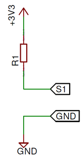
Figure 1: Soil moisture sensor based on a voltage divider.


So, the obvious question here is, "How do I select R1?", and it's a really good question. We need more information, particularly about the soil and distance between our probes (S1 and GND). I chose to use a distance of 15 mm, which means when I construct my sensor the probes must be 15 mm apart. I measured the resistance of my dry soil over a distance of 15 mm and it was about 200 kΩ. I then measured a cup of water's resistance over a distance of 15 mm and it was about 50 kΩ. I need to optimize R1 for those boundary conditions, but before we get too much further into that optimization problem let's explore the expected response of such a sensor. We can derive the relation for the probe voltage:

image

where Vs is the voltage across the sensor probes,

Rs is the soil resistance,

and R1 is our fixed resistance.


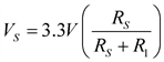
Notice anything non-desirable in the sensor response from this equation? If it's not clear yet, let's choose a value of 100 kΩ for R1 and plot the expected response. Figure 2 shows such a response.


image

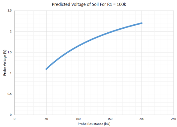
Figure 2: Voltage divider response for soil moisture sensor.


How about now? It's not linear! If I wanted to use this sensor I would have to use a look up table, or a function to linearize the response. This isn't completely out-of-the-norm, and for my original purpose of a high and low threshold triggered system, this would serve the purpose. Since receiving the RPiSoC I wanted to eventually implement the ADC functionality to get a soil moisture percentage, so I would like a linear response. Oh, by-the-way if you indeed wanted to use the divider of Figure 1, you could either treat it as an optimization problem or simply use a spreadsheet to determine the best possible value. This is a common problem, and I've also seen a derivation showing that the optimum value is the square root of the minimum value multiplied by the maximum value. This would be (200k*5k)^(1/2) = 100 k and results in a dynamic range of 2.2/1.1 or 2. It's fairly poor, but if you consider the number of components and ease of setup this may be the result for you. (For a proof of the equation look here: arduino - How would I get a full range voltage reading from a pressure sensor? - Electrical Engineering Stack Exchange)


Let's examine another popular circuit for soil moisture measurement that involves an active device. Figure 3 shows a soil moisture sensor circuit that is quite popular. It's everywhere on the internet, and this is the same circuit that was on the Funduino sensor I "purchased" from DX. There is a good DIY on this type of sensor here: Botanicalls Twitter DIY.


image

Figure 3: Soil moisture sensor implemented using a BJT.


This sensor places the probe resistance into the base resistance, thereby changing the base current as the soil resistance changes. This base current is, obviously, translated into an emitter current and produces an output voltage indicating the soil resistance or moisture level (typical values for a probe separation of 30 mm are R2 = 10kΩ, and R1 = 100Ω). I simulated this sensor for a probe resistance varying between 100kΩ and 400kΩ (probe distance was twice that of my measurements from earlier). Figure 4 shows the results.


image

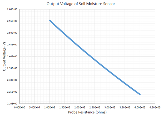
Figure 4: Sensor response from the circuit of Figure 3.


This graph is more appealing because it much more linear than the graph of Figure 2, but I'm bothered by the numbers on the vertical axis. From completely dry to soaked soil there is only a voltage swing of just over 300 mV! I'm not convinced either of the two sensors discussed so far are suitable for an accurate moisture level reading.


So, where shall we go from here? I think we should be able to easily get a dynamic range of 4 since the ratio of dry to wet soil resistance is 4. To do this we need to drive a constant current through our "load", where the load is our soil resistance, and measure the corresponding voltage. It's time to crack open the textbooks (Google) and find a nice current source circuit. Here's one: BJT Current Source. Figure 5 shows the current source modified such that the collector resistor is the soil resistance.


image

Figure 5: Current source soil moisture sensor using a BJT. Output is measured between S1 and S2.


I've set R2 to 10 kΩ and done my analysis to get an appropriate output voltage (S1 to S2) range by using R1 = 40kΩ. There are sites where this same type of analysis has been done, for example: resistors - Choose the resistence with voltage divider sensor - Electrical Engineering Stack Exchange. I've simulated the circuit and the results are shown in Figure 6.


image

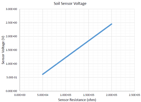
Figure 6: Current source combined with the soil resistance produces a linear output with a dynamic range of 4.


So, there it is; a nice linear output with a dynamic range of 4 (2.5/.625). This is the best I could do in the short time I had; I don't have any diodes yet image, so I will likely have to build the second sensor and "deal with it". Hope this helps anyone designing a soil moisture sensor.

  • Sign in to reply
  • michaelwylie
    michaelwylie over 10 years ago in reply to hlipka

    I think the temperature concern should be addressed before I move forward.

    • Cancel
    • Vote Up 0 Vote Down
    • Sign in to reply
    • More
    • Cancel
  • mcb1
    mcb1 over 10 years ago in reply to hlipka

    Would swapping the probes over using a relay alleviate it ?


    Your design is a good method, but I wonder if you aren't just aiming for the optimum point somewhere.

    If it's above you don't add water, and below you add water.

    Somewhere along whatever slope/line, you decide its time to trigger the watering.


    Since the idea is to deliver to the roots, which should be deep (they are shallow when people only water a small amount), so it won't instantly change.


    I know from my water consent for irrigation, that they allow the equivalent of 4.5 mm of moisture loss due to evapotranspiration.

    The amount of 'water holding capacity' the soil has (80mm in our case) also has a bearing on the amount or frequency of application, since anything more is simply pushed down and is lost.

    These are averages, and that wind can cause just as much or more loss than simply heat.


    So you're battling a number of other factors which may influence the plants use of the available moisture.


    Mark

    • Cancel
    • Vote Up 0 Vote Down
    • Sign in to reply
    • More
    • Cancel
  • hlipka
    hlipka over 10 years ago in reply to michaelwylie

    When you say you want to have an accurate sensor - do you have the means to properly verify and calibrate the measurements you take? How do you know that a certain voltage reading corresponds to a certain soil humidity? From my previous work on that I know that its not exactly easy to do image (I avoided it by using a real humidity sensor [SHT21])

    If you need to do one non-linear approximation, then it doesn't matter much whether all the other relation are linear or not . Especially if you really need to add temperature compensation. I still think that a linear approximation with maybe 5 fixed points can give you easily 10%, maybe even 5% accuracy. (and since the RaspPi can do floating point it will be fast)

    • Cancel
    • Vote Up 0 Vote Down
    • Sign in to reply
    • More
    • Cancel
  • michaelwylie
    michaelwylie over 10 years ago in reply to hlipka

    Sure, electrolysis will cause the probes to corrode, but that's an effect all of these senors are subject to when using DC current. I've seen one example where the galvanized rods were embedded in Plaster of Paris, which may help with corrosion.


    I'm designing a sensor with an end goal of an accurate soil moisture reading. Suppose the soil moisture content to resistance relationship is non-linear, and the response of my sensor is also non-linear. In order to get a corrected reading I now have to correct for two sources of non-linearity. It may be that these two effects together produce a linear relationship (doubtful), but I'm more concerned with the variability in soil moisture resistance with temperature. I may require a temperature compensation stage, but I have not found a good source yet.


    I could use piece-wise linear approximations, but that offloads the complexity of the measurement to the firmware, just as does the non-linear correction. The linear approximation would definitely work, but I'd like to produce a sensor that other people want to use. I think, as a product, it's more desirable to produce a sensor with a linear output than to have users preform corrections via algorithms.

    • Cancel
    • Vote Up 0 Vote Down
    • Sign in to reply
    • More
    • Cancel
  • hlipka
    hlipka over 10 years ago

    One thing to be aware of: when using the soil sensor with DC current, it will corrode sooner or later. You can use high-quality probes (e.g. galvanized rods or stainless steel), or use alternating current.

    One way to do the latter is to connect the propbe not between ground and an input pin, but between two GPIO pins (both with pull-up-resistors). Then for each measurement one pin goes high, and the other is used as input. Next time the other pin goes high, and so on. That way the current flows in alternatrring directions which can greatly reduce corrosion.

    Disadvantage: this doesn't play nice with your method of linearizing the input curve. But OTOH: since the relation between soil moisture and resistance is probably not linear, why do you need to linearize the relation between resistance and measured input voltage? I would just go with, lets say, 4 or 5 different moisture level, and the corresponding input voltages. From these values you can do easily linear approximation (two subtractions, one division) to get the value you need.

    • Cancel
    • Vote Up 0 Vote Down
    • Sign in to reply
    • More
    • Cancel
>
element14 Community

element14 is the first online community specifically for engineers. Connect with your peers and get expert answers to your questions.

  • Members
  • Learn
  • Technologies
  • Challenges & Projects
  • Products
  • Store
  • About Us
  • Feedback & Support
  • FAQs
  • Terms of Use
  • Privacy Policy
  • Legal and Copyright Notices
  • Sitemap
  • Cookies

An Avnet Company © 2025 Premier Farnell Limited. All Rights Reserved.

Premier Farnell Ltd, registered in England and Wales (no 00876412), registered office: Farnell House, Forge Lane, Leeds LS12 2NE.

ICP 备案号 10220084.

Follow element14

  • X
  • Facebook
  • linkedin
  • YouTube