

Table of contents
Abstract
The base for a good free throw is the ball trajectory, which determines the angle the ball enters the hoop. When you train by yourself, it's difficult to assess whether the trajectory is good or not. That's why I devised the SwishMaster!
Project
Introduction
If you have ever played basketball at any level, you’ve probably gotten frustrated with your coach yelling at you to shoot with the right trajectory—meaning the ball should leave your hands at about a 45-degree angle. There are several reasons for this, and here are some of them.
- A higher arc creates a steeper angle of entry into the basket, which effectively makes the hoop “larger.” This gives the ball more room to go in, even if the shot isn’t perfectly centered.
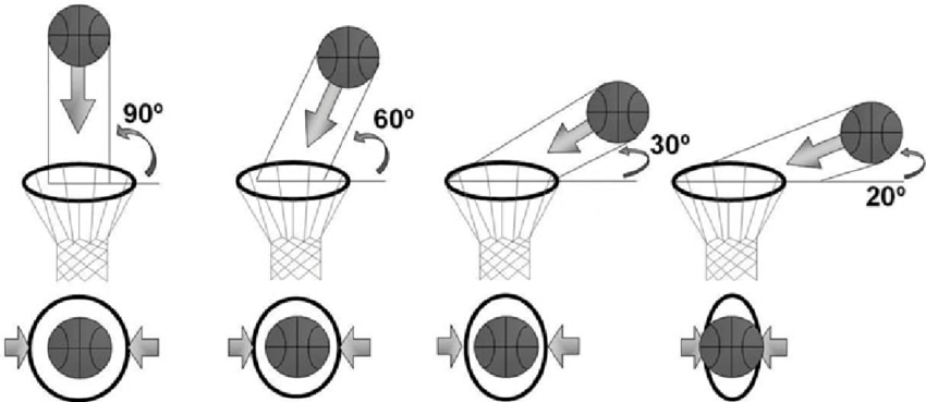
(Source: Okazaki, Victor & Rodacki, Andre & Satern, Miriam. (2015). A review on basketball jump shot. Sports Biomechanics)
- Flat shots hit the rim more often and bounce out. With a proper parabola, the ball has a softer downward path, making it less likely to ricochet.
- A consistent arc helps shooters develop muscle memory. Coaches often emphasize an “ideal arc” (around 45°) for reliable results.
- A higher trajectory makes it harder for defenders to block the ball, especially when shooting over taller players.
- A steep descent means the ball contacts the rim or backboard with less horizontal force, increasing the chances of a “friendly bounce”.
- The right parabola allows long-distance shots (like three-pointers) to retain accuracy, since a flat shot from far away has less chance of success.
I often train by myself, so it’s not easy to make a self-assessment of the arc trajectory. That’s why I devised the SwishMaster
Hardware
To build the SwishMaster device, you need the following hardware components
- An Arduino Nano 33 IoT board. Other boards can be used, as required hardware resources are very limited. You just need
- two digital inputs for the buttons
- two digital I/O for the Utrasonic Sensor Modules
- Optionally, a Bluetooth if you are going to use the mobile app
- A step-up converter, that can generate a voltage in the range from 8 to 18 V, to power the Ultrasonic Sensor Modules
- A level shifter
- Two TDK UltraSonic Sensor Modules
- A 128 x 64 I2C LCD Display
- Two push buttons
- A powerbank
- USB cable
The connections among the components are shown in the following picture
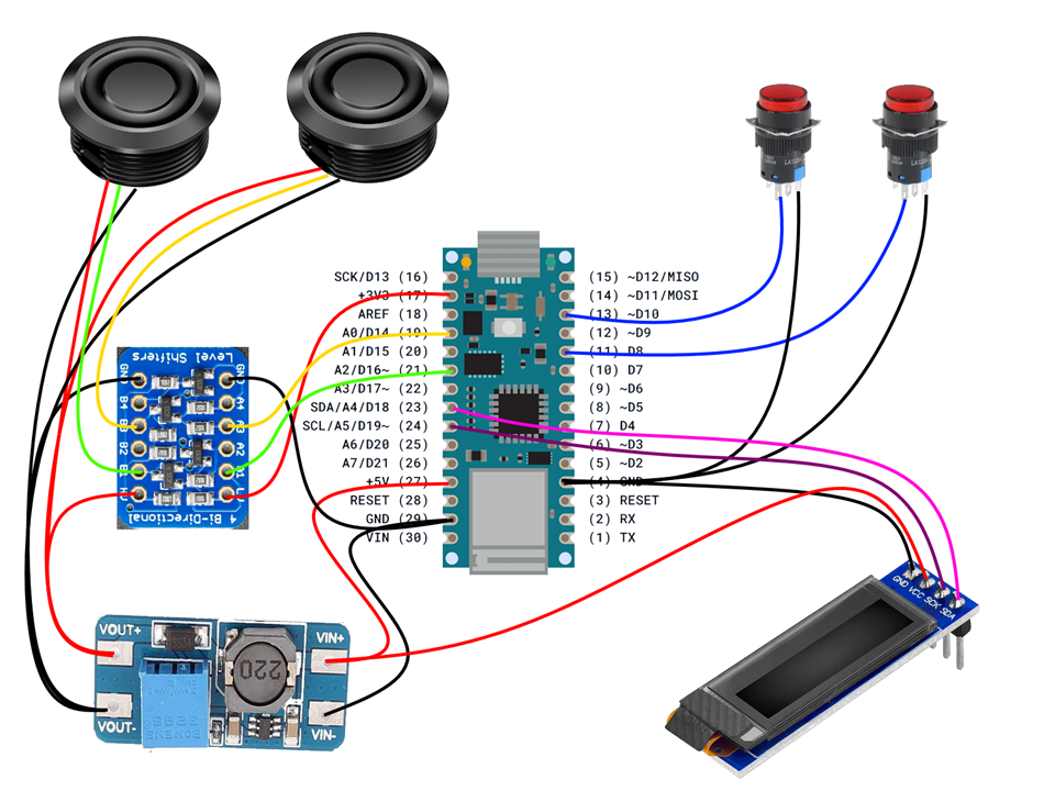
In the following table, the Arduino pins actually used are listed
| Number | Name | Function |
| 4 | GND | Ground for display and push buttons |
| 11 | D8 | Push button 1 |
| 13 | D10 | Push button 2 |
| 17 | +3V3 | Power supply for the low-voltage side of the level shifter |
| 19 | D14 | Trigger/echo USSM 1 |
| 21 | D16 | Trigger/echo USSM 2 |
| 23 | SDA | I2C data (display) |
| 24 | SCL | I2C clock (display) |
| 27 | +5V | Power supply for display and step-up converter |
| 29 | GND | Ground for step-up converter and level shifter |
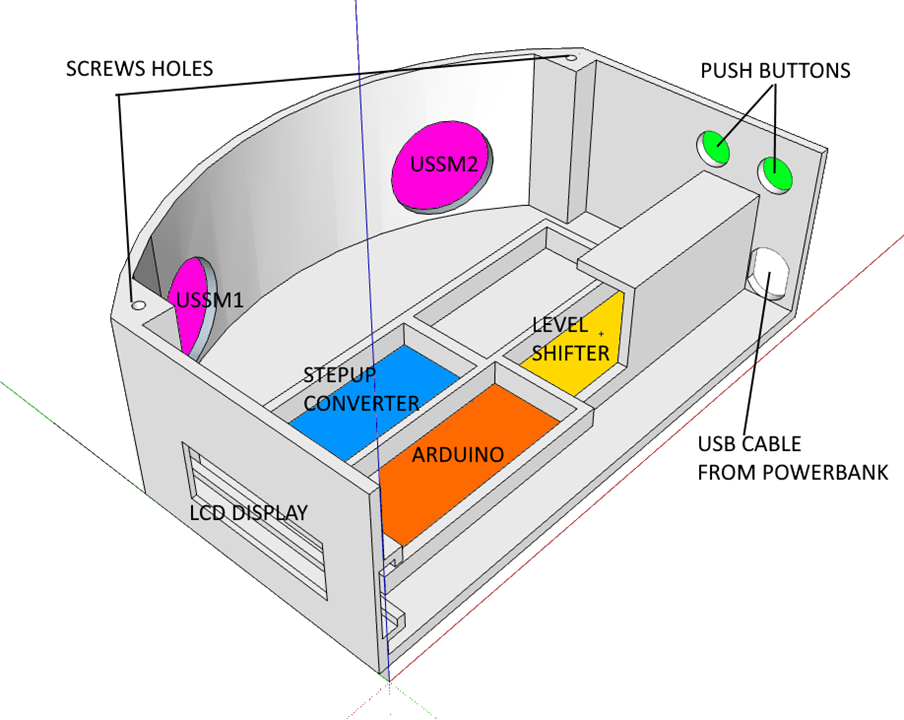
The case
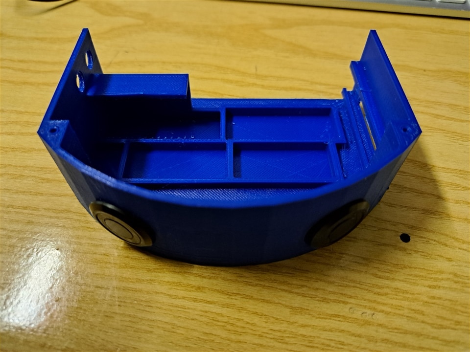
The case has been 3D-printed. The STL and Sketchup files are available on the github repository.
There are three main parts to print
- the case, which hosts all the electronic components
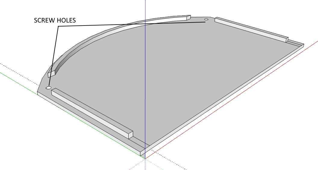
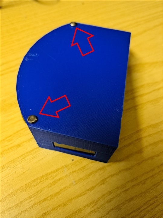
- the cover, which is mounted over the case and is held in place by two screws
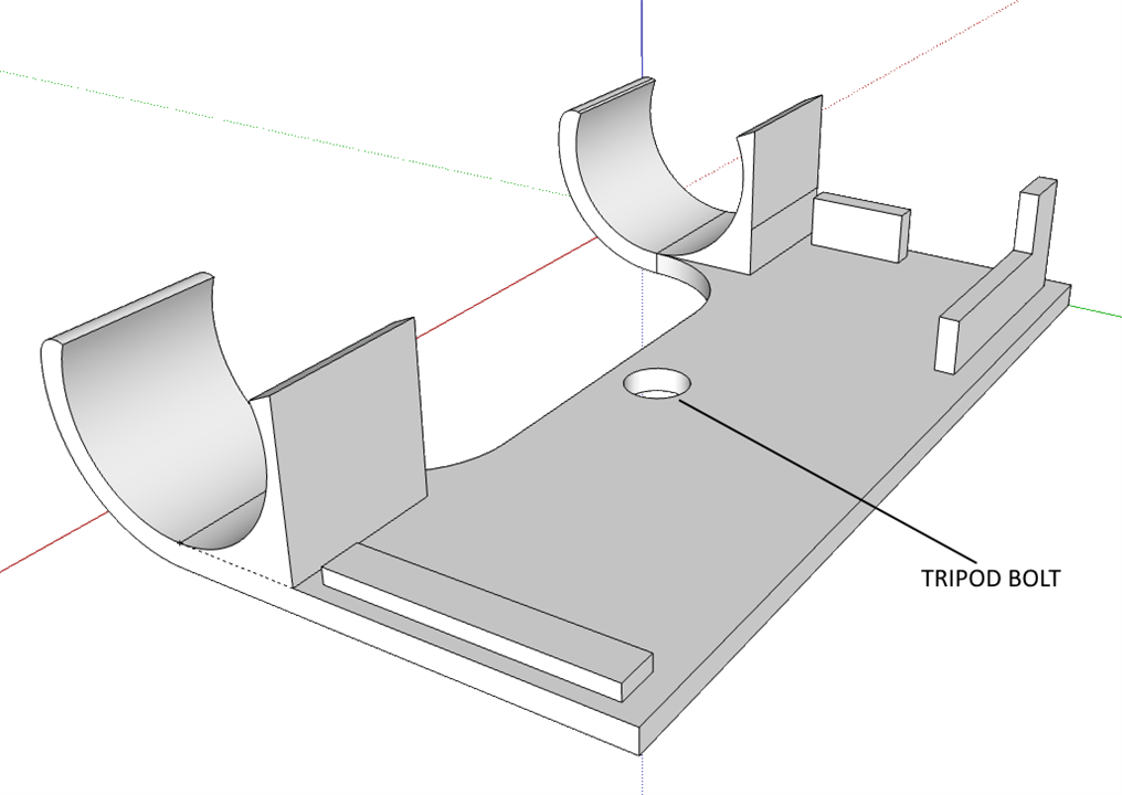
- the base, which has brackets to hold the cylindrical-shaped powerbank
Assembly
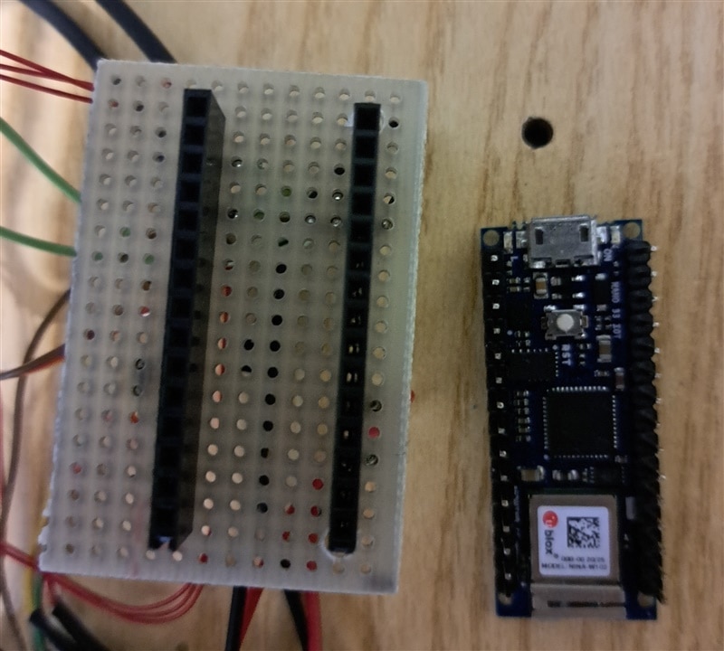
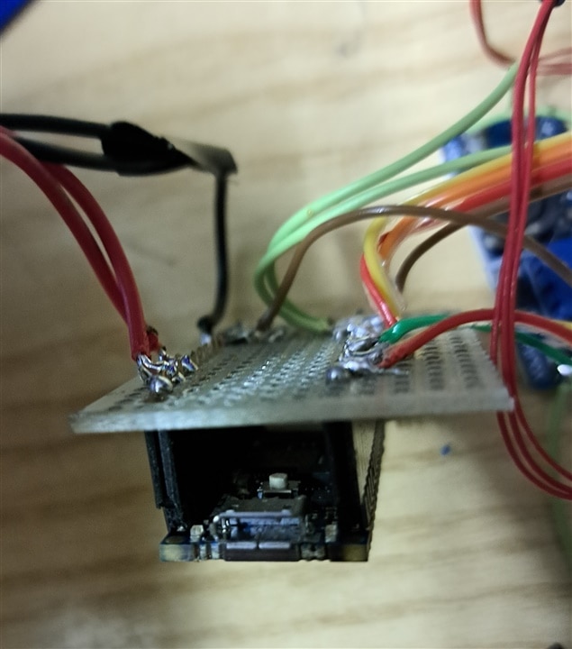
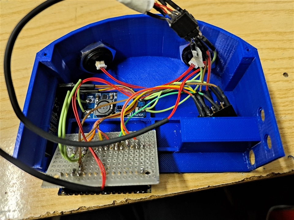
Wire all the electronic boards as shown in the above diagram. I found extremely useful to create a piggy-back board for the Arduino. This board, which is made out of a breadboard, simplifies the soldering process for pins where many wires needs to be connected (for example, ground and power supply)
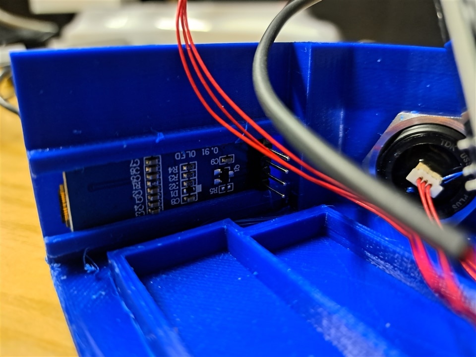
Mount the two USSMs in the two holes on the curved surface of the main case. Use the bolts and gaskets included in the evaluation kit
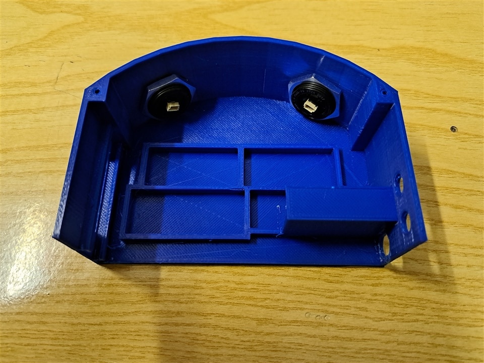
Slide the OLED screen into place. The two guides will help to hold the screen itself in place
Each electronic board can now be placed in its own slot. A piece of double-side tape helps to keep everything safely in place
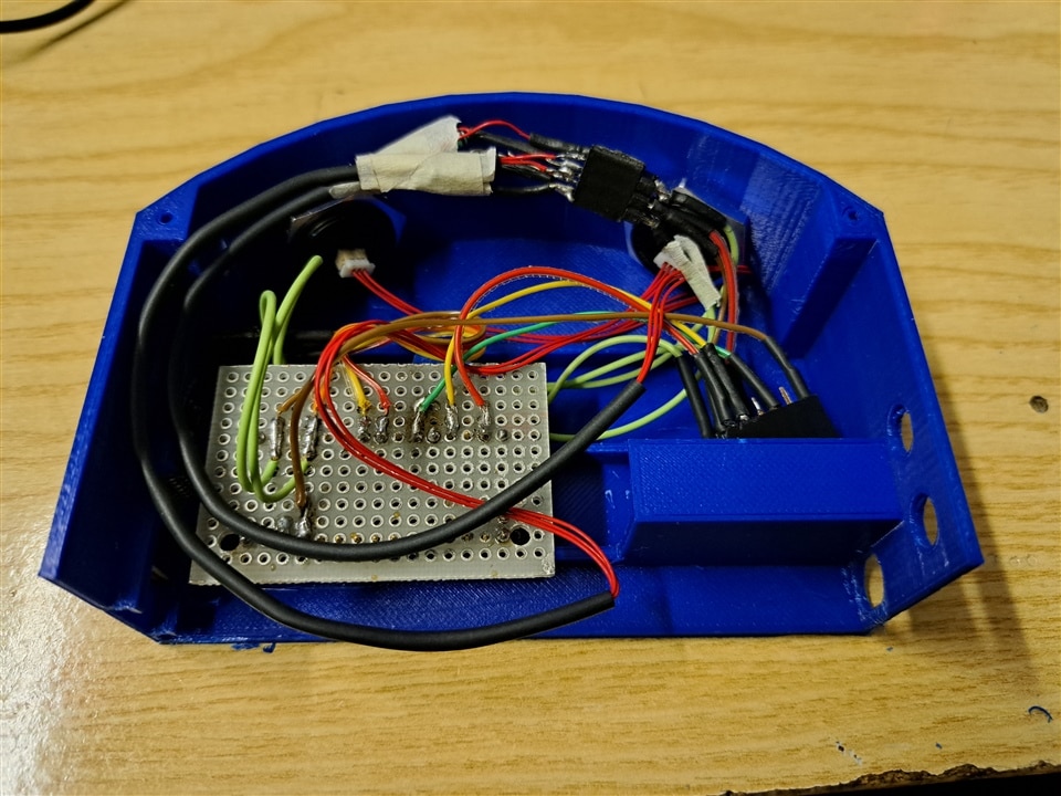
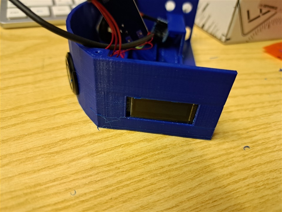
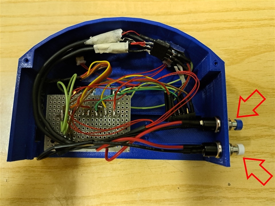
Also the two push buttons can be slid into the designated holes
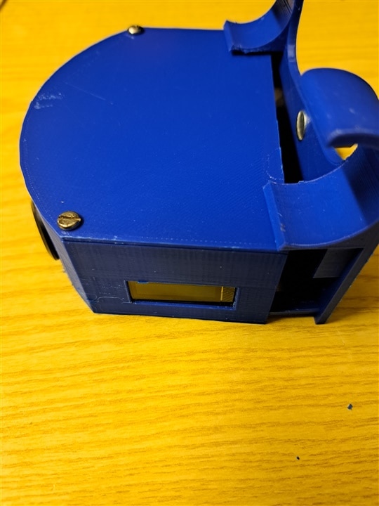
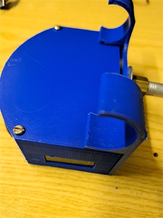
The assembly is completed. Place the cover on the top of the main case and use two screws to keep it firmly in place
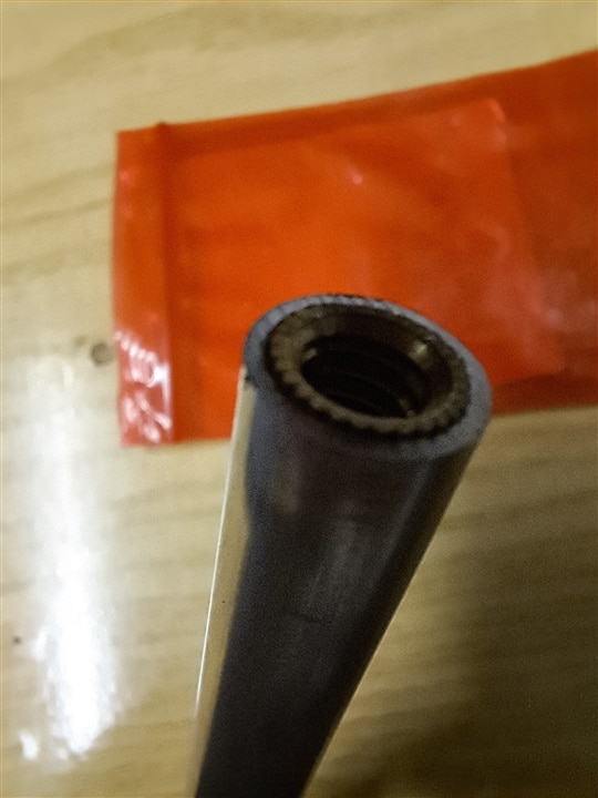
Finally, complete the bottom part. First of all, add a bolt to mount the SwishMaster device on tripod. Tripods have a 1/4 inch (or 20 UNC) screw, so you can gently press a bolt of the corresponding size into the bottom part of the case. In my case, the tripod was not high enough (SwishMaster should stand at 2 meters from the ground, so that it can easily detect the ball at an height of up to 4 meters), so I used an hollow aluminum bar. On one side of the bar, I press-fit the bolt, on the other side I screwed a bolt, as shown in the following pictures.
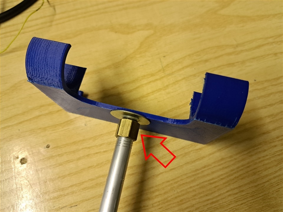
The bottom part should fit perfectly in the space between the case walls but, in case it is loose, some tape is enough to hold it in place.
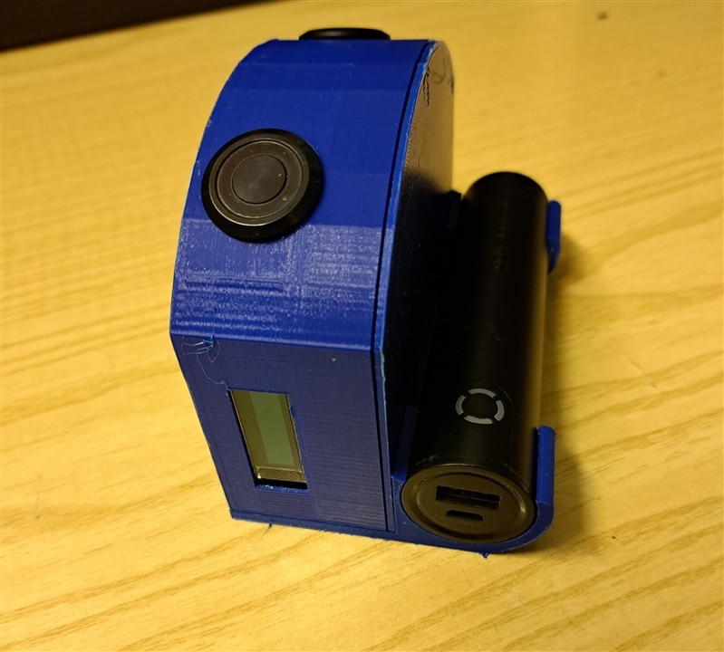
Finally, add the powerbank and connect the USB cable to the powerbank itself and to the Arduino board
Firmware
Arduino program has been developed using Arduino IDE. The libraries required are
- TDK USSM Arduino library, available here. Don't know if it complies with the software license, but you need to make a fix to source code to build it. Mode details are available in this post
- JC_button. This is a simple library to handle button debounce, long-press events, etcetera
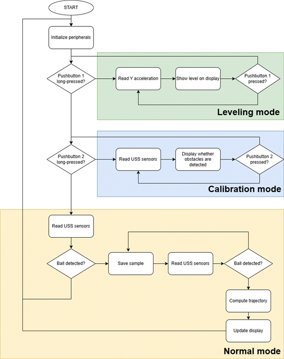
The swishmaster.ino file is the main file, that handles the application state machine, according to the following flow chart
The project includes also a number of classes that implement specific functions. Classes are
SwishMasterBle
Implements the BLE communication with the Android app. It defines a BLE service
BLEService posService("95ff7bf8-aa6f-4671-82d9-22a8931c5387");
The service has the following characteristics
// Ball height. This is a string with the following format: <reading sensor1>,<reading sensor 2>
// When a shot "starts", the value "B" is sent
// When a shot "ends", the value "E" is sent
BLEStringCharacteristic pos("8f0e70fc-2a4b-4fd3-b487-6babf2e220e1", BLERead | BLENotify, 30);
// Parabola "A" parameter, sent after every shot
BLEStringCharacteristic paramA("9f8e4a3b-b5a2-4c19-80f2-23d61b94b1cd", BLERead | BLENotify, 10);
// Parabola "B" parameter, sent after every shot
BLEStringCharacteristic paramB("d19a2f4f-8e2c-4e7c-9a08-44a6b82fbb3d", BLERead | BLENotify, 10);
// Parabola "B" parameter, sent after every shot
BLEStringCharacteristic paramC("a32efc19-f3f9-4a15-8a6f-6e5eab9911d2", BLERead | BLENotify, 10);
// Maximum height, sent after every shot
BLEStringCharacteristic maxHeight("c04b882e-d318-46fa-a8e4-dc5c2b6e9cf1", BLERead | BLENotify, 10);
// Angle of entry, sent after every shot
BLEStringCharacteristic angle("e3a7b2df-4d9c-46e7-9a5b-b61d24c8e05a", BLERead | BLENotify, 10);
The class defines the following methods
class SwishMasterBle {
public:
  SwishMasterBle ()
  {}

  // Empty destructor
  ~SwishMasterBle() = default;

  bool setup();
  // Send the "start of shot" message
  void start();
  // Send the "end of shot" message
  void stop();
  // Send sensors readings
  void point(float h1, float h2);
  // Send shot parameters
  void result(double a, double b, double c, double h, double an);

private:
};
SwishMasterDisplay
Implements functions to show application data on the 128x32 OLED display
class SwishMasterDisplay {
public:
SwishMasterDisplay ();
// Empty destructor
~SwishMasterDisplay() = default;
bool setup();
Adafruit_SSD1306& display() { return _display; }
void drawBitmap(int x, int y, int bitmap);
void clear();
void update();
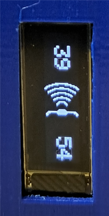
void showHeight(long h1, long h2);
void showAcquiring();
void showData(float a, float h, float angle);
void showResult(bool aOk, bool hOk, bool angleOk);
void showLevel(float angle);
void showCalib(long h1, long h2);
void showLogo();
private:
Adafruit_SSD1306 _display;
};
SwishMasterDataBuffer
Implements an helper class to store USSMs readings and to perform coordinate corrections. More details in this post
typedef struct {
float x;
float y;
} Point;

typedef struct {
int n;
Point points[MAX_SAMPLES];
} DataBuffer;

class SwishMasterDataBuffer {
public:
SwishMasterDataBuffer ();

// Empty destructor
~SwishMasterDataBuffer() = default;

bool setup();
// clear all samples in the buffer
void clear();
// store a sample for the given sensor (0 or 1)
void update(int sensor, long _y);
// no more samples, apply corrections
void done();
// return number of samples in the final buffer
int numSamples();
// return the sample at the given index
Point getSample(int index);

private:
void applyCorrections(int sensor, DataBuffer* buffer);
float averageHeight(DataBuffer* buffer);
float computeWidth(float y);
void printBuffer(DataBuffer* buffer);
void sortCoords(DataBuffer* buffer);

DataBuffer buffers[NUM_SENSORS];
DataBuffer corrected;
};
SwishMasterParabola
Implements the algorithm that computes the parameters of the parabola that best fits the input points. More details in this post
struct Parabola {
  float a;
  float b;
  float c;
};

class SwishMasterParabola {
public:
  SwishMasterParabola ();

  // Empty destructor
  ~SwishMasterParabola() = default;

  bool setup();
  // clear data points
  void clear();
  // add a new point to the buffer
  void update(float x, float _y);
  // return calculated parabola parameters
  Parabola fit();
  // return angle of entry
  float angle(Parabola p);
  // return maximum height
  float maxHeight();

private:
  Parabola _fit();

  int n;
  float x[MAX_SAMPLES];
  float y[MAX_SAMPLES];
  float maxY;
};
Operating manual
The SwishMaster is absolutely easy to use
- Mount the SwishMaster on a tripod. Because the range of the Ultrasonic Sensors is about 2 meters, the SwitchMaster must be placed at an height of about 2 meters. In this way, we can track the ball up to an height of about 4 meters above the gorund
- Power up the device.
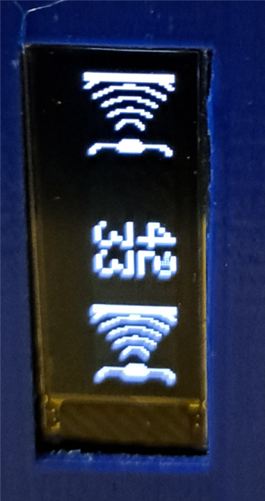
- The device automatically enters "Calibration mode"
- Position the SwishMaster so that the display two "Success"
 icons. This means that no obstacles are in the range of the sensors, and ball can be reliably detected
 - Push the bottom button to enter "Working mode"
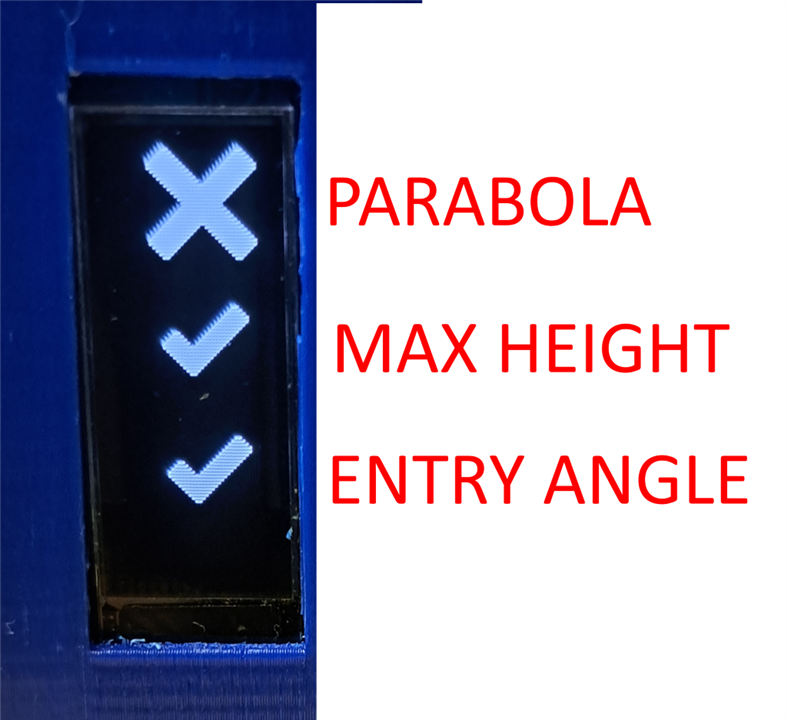
- Throw your free throw and check the rating. Three icons are shown, each of which can be either "Success" or "Fail"
 . From top to bottom, we have
- Parabola: the parabola is considered correct if the calculated "a" parameter of the parabola is above 0.015
- Maximum height: height is considered correct if the maximum height is above 3.3 meters
- Angle of entry: angle is considered correct if it ranges from 40 to 65 degrees
Mobile app
Mobile app makes it easier to check shot ratings, thanks to a richer user interface.
App code is not particularly interesting. All the application logic is in the following classes
- in
DeviceActivity, I overrode methods of the classBluetoothGattCallbackto get notifications when the SwishMaster device publishes new values - The
DrawSurfaceViewis the class where the detected positions and estimated parabole is drawn. Here, I used the basic drawing methods of theCanvasclass - The
ParabolaDataViewshows the calculated parabola parameters. Again, I leveraged theCanvasclass to compose the pane content
To build the mobile app, simply download the source code from github repository, open with Android Studio, build and deploy to your phone.
Using the mobile app is very simple. Launch the app, and it will start scanning for SwishMaster devices

When a SwishMaster device is detected, app will automatically connect. Every time you make a shot, SwishMaster device will transfer ball positions and trajectory parameters through BLE to the mobile app. Data will be shown on the screen for an easy review

Here the three success/fail icons have the same meaning as on the display of the Swishmaster device. From left to right, we have
- Parabola
- Maximum height
- Angle ot entry
Below the icons, the calculated values of each parameter are shown
Final demo
Wrap up
The feedback the SwishMaster device provides is, in my opinion, good but there are some important limitations that affect the calculation of the 'a' parameter (which defines whether the trajectory is good or not). The major limitation is that the USSMs does not provide reliable and consistent measures on a moving object, especially it the object is moving as fast as a ball. My initial hope was that the approach based on the interpolation of available data with a quadratic equation would have smoothed out all these errors. However, during the tests on field, I realized that this is simply not true. Let me explain. I added a data logging function to the mobile app, so that all detected ball heights was saved on my mobile phone in a file in the Downloads folder. I used the collected data to improve the algorithm but I immediately realized that, just adding even a small error (just a 2% error is enough) on a few points, leads to completely different trajectory prediction.
To overcome this limitations, I tested two different solutions
First, I tried to increase the number of points used in the interporlation function. The problem is that there is a physical limit to the number of samples I can take. The limit is related to
- the maximum acquisition rate of the USSM: according to my experiments, a pause of at least 10 ms is required between two readings in order to get reliable and accurate measurements. Without the pause, the measurements show a significant increase in the variance
- the time-of-flight of the ball. It takes about 800 ms for the ball to reach the backboard, and the SwishMaster does not cover the whole path from player's hand to backboard. Assuming that the SwishMaster can "see" the ball for just 500 ms, the maximum number of positions that can be read is less than 10
As a second attempt, I tried to train a neural network on Edge Impulse. The idea was to feed the neural network with the ball positions and get whether the trajectory arc is good or not as an output. This work is still in progress, but looks like the decision regions have clean boundaries. I shot about 100 free throws, half with a good arc and half almost flat. The detected positions for each shot have been saved in a CSV ifle and uploaded to Edge Impulse.
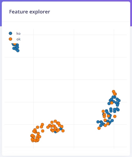
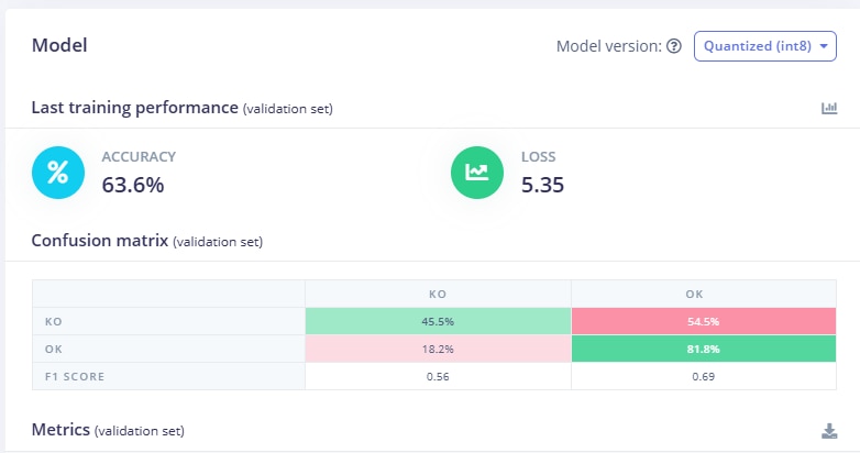
If I use the output of my current trajectory analysis algorithm to label the samples, the output is quite poor...
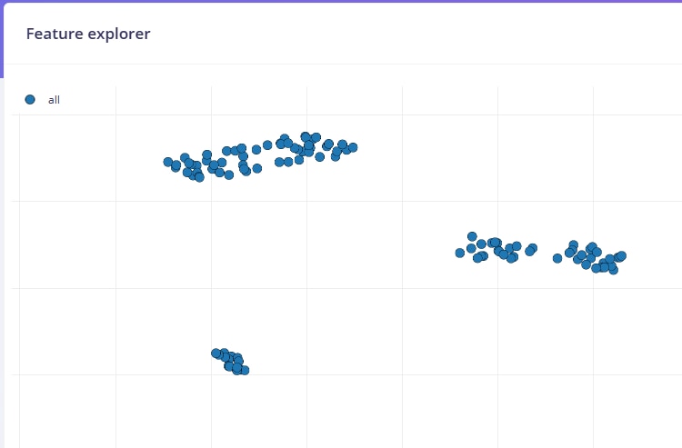
But if I let Edge Impulse extract features from dataset, we can identify two well separated decision regions
For this reason, I am confident an approach based on the EdgeImpulse platform and a neural network could possibly achieve a better accuracy compared to the approach based on a quadratic equation.
However, the thought that will keep bothering me in the month to come is why I drive signal from USSM to ground. I tried on all possible values of pull-up resistors, and the possible configuration of the input pin on the Arduino board, but yet the maximum I could achieve is shown in the following screenshot. I was able to read distances, but the idea of not having a clean signal is quite disturbing
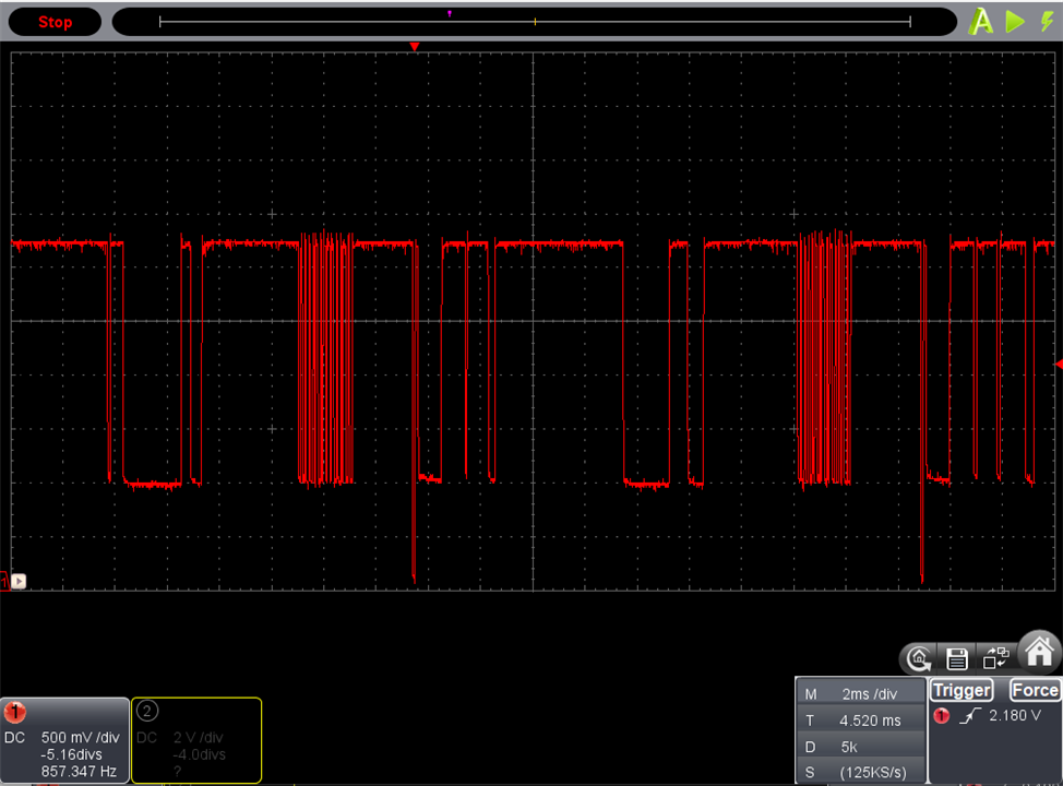
But there is a thought that bothers me event more... how this can even work? How Arduino can capture the low state of the digital input??
Conclusions
At the end of this challenge, I would like to thanks TDK for giving all the challengers the opportunity to work on their Ultrasonic Sensor Modules.
As in every Deisgn Challenge, it was fun to experiment and build with new components and technologies. The TDK Ultrasonic Sensor Modules have proven to be very powerful and versatile. Unfortunately, when I proposed my project I was not aware of all the features and capabilities of these sensors, so the project I built just scratched the surface of what can be achieved. Should I go back in time, I would think about a project that can show the most relevant features of this product, namely
- the mechanical resistance to vibrations and water
- the flexibility provided by the integrated ASIC, in terms of thresholds programmability and multi-object tracking
In any case, thanks for reading my posts and thanks for your comments! Really appreciate it!
References
USSM datasheet
Evaluation kit datasheet
USSM GUI
E542.33 datasheet
Arduino library
https://www.tdk-electronics.tdk.com/en/3105452/design-support/design-tools/ussm/ussm-arduino-library
github repositories
Arduino sketch https://github.com/ambrogio-galbusera/swishmaster
Android app https://github.com/ambrogio-galbusera/swishmaster-android
STL files https://github.com/ambrogio-galbusera/swishmaster-stl
Blog posts
SwishMaster - #1 - Introduction
SwishMaster - #2 - The evaluation kit
SwishMaster - #3 - Experimenting with the USSM
SwishMaster - #4 - Connecting USSM to Arduino
SwishMaster - #5 - Ball trajectory
SwishMaster - #6 - Hardware assembly
SwishMaster - #7 - Miscellaneous