


Echo Park – Ultrasonic Parking Assistant
Introduction
This is my initial post in the In Reach! Ultrasonic Sensor Sensing Challenge.
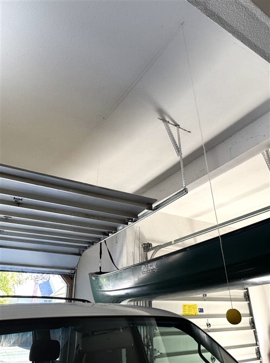
I have a requirement for a parking assistance indicator that will indicate when a vehicle is parked at the appropriate position in a residential two car garage. Many cars and trucks built in the last 5-10 years have collision avoidance sensors and/or cameras to indicate that they are at a safe distance into the garage. I own a couple of older vehicles that do not have those sensors and have been using the old ball and string technique that lowers a ball from the ceiling when the garage door opens to indicate the correct parking position. The TDK Ultrasonic Sensor provides an opportunity for me to create a modern and more reliable parking system with visual and audible indicators.
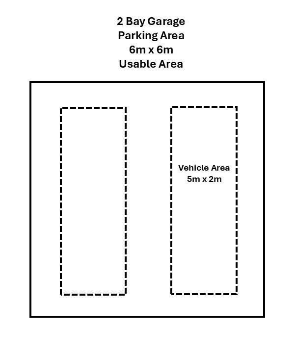
The diagram below shows the usable parking area in the garage and the relative size of my vehicles. I have added shelving and storage areas that have limited the area to this size which fits smaller SUVs and passenger cars – so no trucks or large SUVs in the future for me.
The ball and string method is cheap and fairly dependable, though it occasionally gets stuck. Another consideration is that the ball location need to be adjusted to correspond with the height and position of the vehicle windshield.
Project Description
The challenge kit includes a TDK USSM Demo board and 2 USSM1.0 PLUS-FS ultrasonic pulse echo sensors. The sensors that have a detection range of 18 cm to 5 m when used in solo (independent) mode and can-do close range (4 cm) detection when two or more sensors are used pitch-and-catch mode. My garage has a usable depth of 6 m and my maximum vehicle length is 5 m, so my parking distance is about 60 cm ( I prefer more clearance in the front of the vehicle). I will be using the sensors in solo mode to provide independent parking positions for two vehicles.
The initial operation and characterization of the sensors will be done using the USSM Demo board then the actual project will use the sensor with a standalone MCU and supporting peripherals. I will use a Seeed Xiao ESP32-S3 Sense as the MCU. It will be mounted on a Xiao Expansion board. This configuration will provide a camera, OLED display, buzzer, real-time clock (RTC), Grove interfaces for RGB LEDs, and WiFi/BLE communication. For this challenge I am only building the first of the two units.
Project Plan
Sensor Characterization
System Design
- Block Diagram
- Bill of Materials
- Wiring Diagram
- Integration
- 3D Print Housing
- Software Design
- Test
Risks
The are two areas of concern that I have regarding this project:
- Power - the USSM sensor uses a 8V to 18V power supply and the ESP32-S3 uses 3.3V. I plan to power the Xiao ESP32-S3 from the 5V USB power and use a boost converter to get the 12V required for the sensor from the 3.3V output from the Xiao (I may want to try a battery powered configuration later). I'll need a bi-directional IO level converter for the single serial IO signal between the ESP32-S3 and the sensor.
- Proprietary sensor communication protocol - the USSM sensor uses a proprietary single wire bi-directional serial UART protocol to send and receive data to/from the MCU. There is a library available for the Arduino IDE that has been tested with a few Arduino MCUs. It may require some tweaking to get it to work with the ESP32-S3.
Delivery
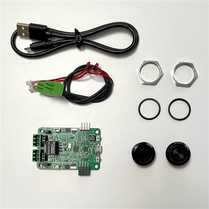
I received the TDK Demo Kit earlier this week. It includes the components shown below:
- TDK Demo Board
- USB-A to micro-B cable
- Two Ultrasonic Sensor Modules
- Two sensor cables
- Two gaskets and nuts
Next step - sensor characterization.


