


Sensor Characterization Setup
I have used a lot of the simple HC-SR04 Ultrasonic Ranging Modules that have similar range capabilities (2cm-4m). These modules use separate send and receive elements and provide the transmit and receive circuits but use an external MCU to do the time-of-flight calculations. The MCU sends a trigger pulse and receives an echo pulse. It provides the timing to determine the roundtrip time and calculates the distance. These modules operate at 40KHz and are not configurable. They are easy to use (just program the MCU using one of many available libraries) and they just seem to work with moderate accuracy.
So, I was very interested in testing the TDK USSM1.0 PLUS-FS module, which uses the elmos E524-33 ASIC. This is a pulse-echo module that uses a single piezo sensor for sending and receiving (to measure very short range (4cm), two modules can be used to send/receive). The module operates at 74.5 KHz and has a single sensor range of (18cm-5m).
This is a highly configurable module that can be tuned for specific measurement environments. The following parameters can be adjusted:
- Transmit Burst Power: Adjusts the energy of the ultrasonic pulse. Higher power is generally used for longer ranges.
- Receiver Sensitivity (Gain): Controls how faint an echo the sensor can detect. Higher sensitivity is needed for longer ranges, while lower sensitivity helps prevent false echoes from nearby objects. The E524.33 features advanced settings for the dynamic gain curve.
- Threshold Levels: Digital signal processing compares the received echo against programmable threshold levels. You can set a primary and a secondary threshold.
- Burst Length and Frequency: Defines the duration and frequency of the ultrasonic pulse.
- Damping Algorithm: For near-field measurements, the "Smart Damping" algorithm can be configured to minimize the transducer's "settling time" or "blind zone" after transmitting the burst.
This configurability is a blessing and a curse. This is certainly not a point and shoot sensor. I was somewhat surprised when I set up the Demo Kit on my desk, pointed it at a large cardboard panel about 160cm away and got very noisy readings using the Streamout measurement although the average value was correct. I moved the panel back to 175cm and got similar results. Here are a couple of short videos of the Streamout plots.
I then decided to try the measurements out in the hallway next to my office and the results were so bad that the average value was not monotonic as I varied the range. Here’s a plot of the sensor pointed at the door at the end of the hall at about 135cm.
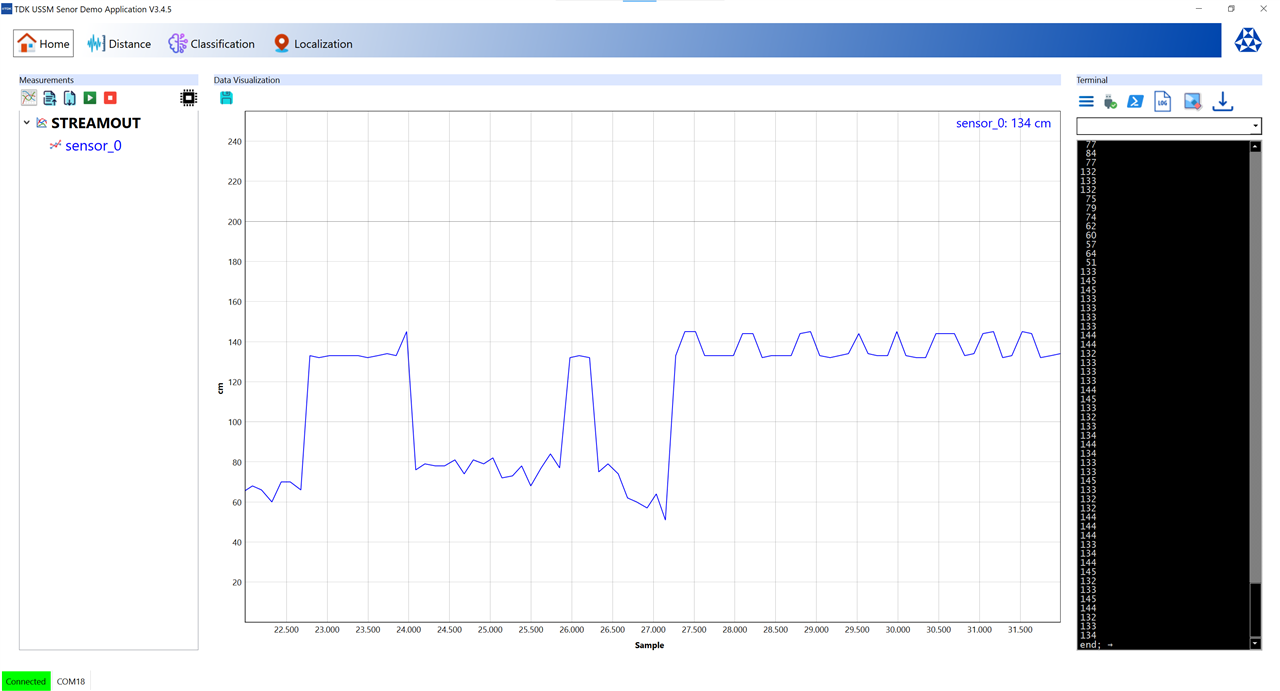
I realized that the default threshold and gain settings were not correctly configured for my measurement setup and that I was detecting lots of multipath reflections.
The sensor specification indicates that the reference target is a cylindrical pole, 75mm diameter, 1m height. That should provide a good primary reflection and scattering of any of the sound waves that do not strike perpendicular to the target. That should minimize the amplitude of multipath reflections.
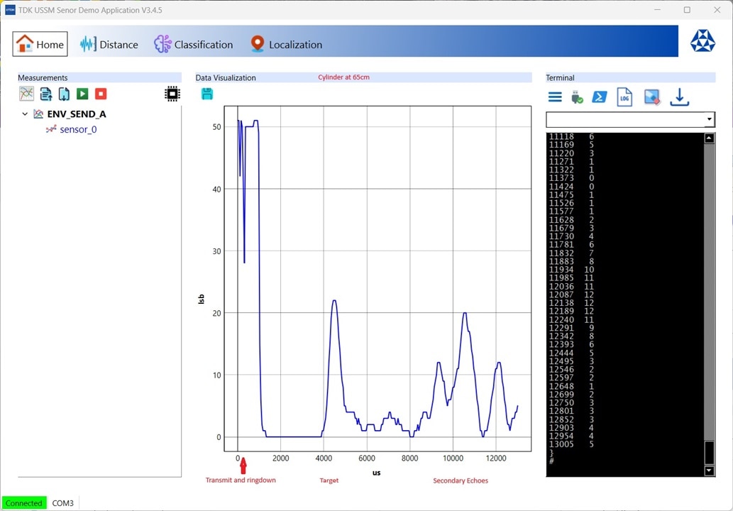
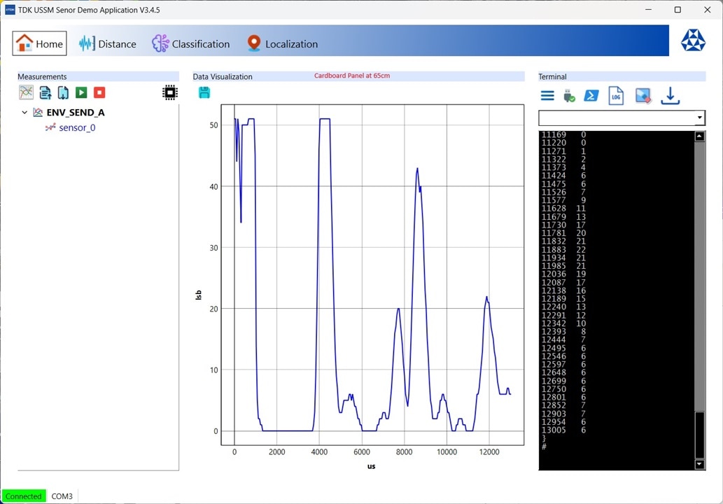
To test this out I used the Envelope measurement which provides an analog measurement of the amplitude and time of received echoes.
Here is a comparison of the Envelope measurement of a cylinder and a cardboard panel at 65cm. In the initial 1000us or so of both plots you see the initial transmission pulse and the ringdown period (time for the piezo element to settle). During this period the receiver is clipping. The target reflection occurs around 4000us and in the case of the cardboard panel the echo is strong enough to drive the receiver to clip while in the case of the cylinder it only has around 40% of that amplitude. The secondary multipath reflections are also significantly larger for the cardboard panel. The secondary reflections are also a lot earlier in time. This demonstrates that if the receiver gain and threshold are set for a faraway target that a near target measurement will suffer from significant multipath noise. Or if there is no near target it could mistake a multipath echo in its field of view (FOV) as the target. The shift in time of the secondary reflections shows the effect of the shape and size of the target surface relative to the location of other reflecting surfaces in the environment.
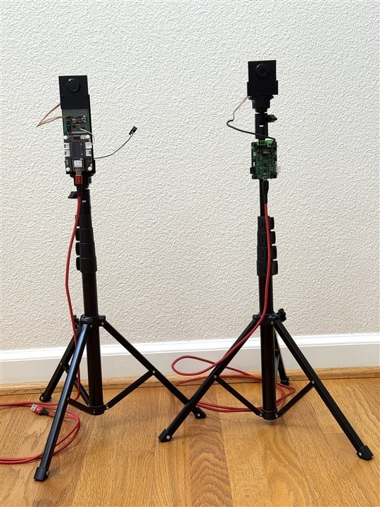
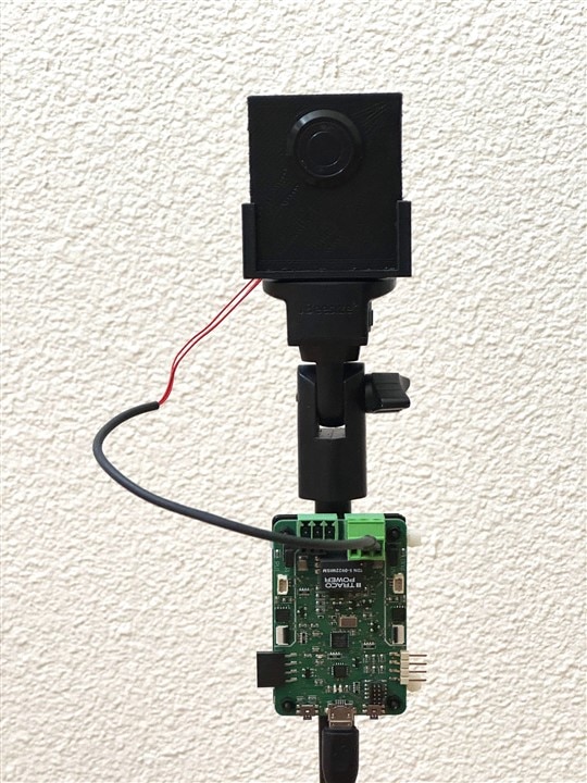
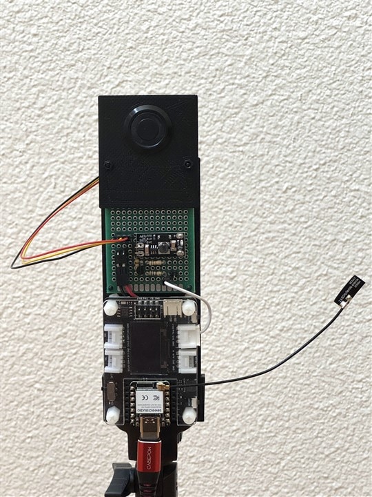
My project target is the front of a vehicle which is not solid or flat, so it is obvious that I will need to do my sensor characterization and parameter tuning in the garage with the vehicle (I’ll ignore for the moment that different cars may have different profiles). To that end, I built two tripod mounted measurement setups. The kit has two sensors, and I am doing single sensor measurements, so I have one sensor attached to the Demo Board so that I can leverage the capabilities of the Demo GUI software and I have the other sensor attached to the Xiao ESP32-S3 in my project configuration in order to test my application program.
The USSM sensor internal registers contain the following information:
- ID, EEPROM, Wakeup, Standby
- Sensor calibration
- Measurement configuration
- Threshold setting for profiles A and B. C uses one of them
- Status: measurement context and feedback, near-field flag
- Temperature
These registers contain 93 values that are stored in volatile memory.
There is also non-volatile EEPROM memory that stores the factory calibration data. After power-up the calibration data is copied into the volatile memory, and the default values are written to the Measurement Setup and Threshold Setup A/B registers.
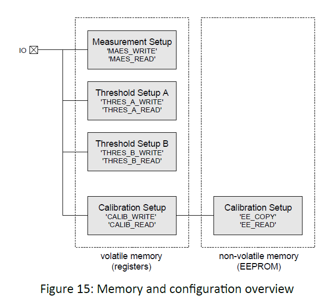
The 4 registers "Measurement Setup", "Threshold Setup A", "Threshold Setup B" and "Calibration Setup" are used to configure the device. During characterization I’ll need to determine the correct measurement modes and threshold values. These values will need to be written to registers after power-up.
The Threshold Setups allow the configuration of 10 Threshold vs Time zones that set the detection sensitivity at different distances. The default values lower the detection thresholds as distance increases. Not sure about why the final threshold is 0 lsb, but I'll check that out.
TdkUssm[1].THRESHOLD_A[20] = {
0 | 75 | 5 | 31 |THVAL_A1 | 31 | 155.000 lsb |THVAL_A1
1 | 72 | 3 | 1 |THPOS_A1 | 1 | 256.000 us |THPOS_A1
2 | 67 | 5 | 15 |THVAL_A2 | 15 | 38.000 lsb |THVAL_A2
3 | 64 | 3 | 2 |THPOS_A2 | 2 | 512.000 us |THPOS_A2
4 | 59 | 5 | 15 |THVAL_A3 | 15 | 38.000 lsb |THVAL_A3
5 | 56 | 3 | 2 |THPOS_A3 | 2 | 512.000 us |THPOS_A3
6 | 51 | 5 | 10 |THVAL_A4 | 10 | 22.000 lsb |THVAL_A4
7 | 48 | 3 | 2 |THPOS_A4 | 2 | 512.000 us |THPOS_A4
8 | 43 | 5 | 10 |THVAL_A5 | 10 | 22.000 lsb |THVAL_A5
9 | 40 | 3 | 4 |THPOS_A5 | 4 |2048.000 us |THPOS_A5
10 | 35 | 5 | 10 |THVAL_A6 | 10 | 22.000 lsb |THVAL_A6
11 | 32 | 3 | 4 |THPOS_A6 | 4 |2048.000 us |THPOS_A6
12 | 27 | 5 | 5 |THVAL_A7 | 5 | 11.000 lsb |THVAL_A7
13 | 24 | 3 | 4 |THPOS_A7 | 4 |2048.000 us |THPOS_A7
14 | 19 | 5 | 5 |THVAL_A8 | 5 | 11.000 lsb |THVAL_A8
15 | 16 | 3 | 5 |THPOS_A8 | 5 |4096.000 us |THPOS_A8
16 | 11 | 5 | 5 |THVAL_A9 | 5 | 11.000 lsb |THVAL_A9
17 | 8 | 3 | 5 |THPOS_A9 | 5 |4096.000 us |THPOS_A9
18 | 3 | 5 | 0 |THVAL_A10 | 0 | 0.000 lsb |THVAL_A10
19 | 0 | 3 | 5 |THPOS_A10 | 5 |4096.000 us |THPOS_A10
My initial plan had been to use the full 5m range of the sensor to track the vehicle from the point where it entered the garage up to its parking position. It seems that it might require me to dynamically change the gain and threshold profile to reliably track it. I’ve decided that initially I’ll just characterize and track the final 2m.
I’ll describe my project configuration and measurement characterization results in future posts.
Note: Other challengers have been doing a good job of describing the sensor and kit specifications and operation using excerpts of the user and reference manuals, so I won’t include a lot of redundant information. I’ll reference specific features and specifications when they are unique to my project.
