element14 Community
element14 Community
    Register Log In
  • Site
  • Search
  • Log In Register
  • About Us
  • Community Hub
    Community Hub
    • What's New on element14
    • Feedback and Support
    • Benefits of Membership
    • Personal Blogs
    • Members Area
    • Achievement Levels
  • Learn
    Learn
    • Ask an Expert
    • eBooks
    • element14 presents
    • Learning Center
    • Tech Spotlight
    • STEM Academy
    • Webinars, Training and Events
    • Learning Groups
  • Technologies
    Technologies
    • 3D Printing
    • FPGA
    • Industrial Automation
    • Internet of Things
    • Power & Energy
    • Sensors
    • Technology Groups
  • Challenges & Projects
    Challenges & Projects
    • Design Challenges
    • element14 presents Projects
    • Project14
    • Arduino Projects
    • Raspberry Pi Projects
    • Project Groups
  • Products
    Products
    • Arduino
    • Avnet Boards Community
    • Dev Tools
    • Manufacturers
    • Multicomp Pro
    • Product Groups
    • Raspberry Pi
    • RoadTests & Reviews
  • Store
    Store
    • Visit Your Store
    • Choose another store...
      • Europe
      •  Austria (German)
      •  Belgium (Dutch, French)
      •  Bulgaria (Bulgarian)
      •  Czech Republic (Czech)
      •  Denmark (Danish)
      •  Estonia (Estonian)
      •  Finland (Finnish)
      •  France (French)
      •  Germany (German)
      •  Hungary (Hungarian)
      •  Ireland
      •  Israel
      •  Italy (Italian)
      •  Latvia (Latvian)
      •  
      •  Lithuania (Lithuanian)
      •  Netherlands (Dutch)
      •  Norway (Norwegian)
      •  Poland (Polish)
      •  Portugal (Portuguese)
      •  Romania (Romanian)
      •  Russia (Russian)
      •  Slovakia (Slovak)
      •  Slovenia (Slovenian)
      •  Spain (Spanish)
      •  Sweden (Swedish)
      •  Switzerland(German, French)
      •  Turkey (Turkish)
      •  United Kingdom
      • Asia Pacific
      •  Australia
      •  China
      •  Hong Kong
      •  India
      •  Korea (Korean)
      •  Malaysia
      •  New Zealand
      •  Philippines
      •  Singapore
      •  Taiwan
      •  Thailand (Thai)
      • Americas
      •  Brazil (Portuguese)
      •  Canada
      •  Mexico (Spanish)
      •  United States
      Can't find the country/region you're looking for? Visit our export site or find a local distributor.
  • Translate
  • Profile
  • Settings
In the Air Design Challenge
  • Challenges & Projects
  • Design Challenges
  • In the Air Design Challenge
  • More
  • Cancel
In the Air Design Challenge
Blog Carbon Footprint Monitoring - Power Meter CT
  • Blog
  • Forum
  • Documents
  • Polls
  • Files
  • Events
  • Mentions
  • Sub-Groups
  • Tags
  • More
  • Cancel
  • New
  • Share
  • More
  • Cancel
Group Actions
  • Group RSS
  • More
  • Cancel
Engagement
  • Author Author: xever
  • Date Created: 28 Jan 2015 6:33 PM Date Created
  • Views 1088 views
  • Likes 1 like
  • Comments 3 comments
  • cc3200_power_meter
  • iot_footprint
  • internet_of_things
  • in_the_air
Related
Recommended

Carbon Footprint Monitoring - Power Meter CT

xever
xever
28 Jan 2015

Household energy consumption could be the highest contributor in one's carbon footprint.  By measuring how much energy we consume each day we may be able to adjust our usage patterns to save.  There are several ways to measure household energy, both invasive and non-invasive methods.  In this project, the focus will be on non-invasive method, specifically using a split core type current transformer sensor to create a power meter.  Hall-effect is another type of non-invasive method, such as using the ACS712 chip, which will be blogged another time.

image


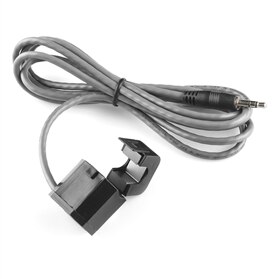
(Current transformer) CT sensors are used to measure alternating current.  As any transformer, it has a primary winding, a magnetic core and secondary winding.  Split-type CTs can be clamped around the supply line of an electrical load to tell how much current is flowing through it.  It does this by acting as an inductor and responding to the magnetic field around the current carrying conductor.  In this case the primary will be the live or neutral wire (not both) and passed through the hole of the CT sensor.  The secondary is made up of multiple fine wires enclosed inside the transformer.  By reading the amount of current being produced by the coil, we can then calculate how much current is passing through the conductor. 


The CT sensor used in this project is a current output type and for this data to be useful, the induced current needs to be converted to voltage using a burden resistor.  This specific sensor has the following characteristics: 30A nominal, 60A maximum rated primary current and 2000 turns ratio.


The blog post in this link has a good explanation in the circuit design process and will be used as a guideline in designing a power meter for Texas Instrument's CC3200 Launchpad XL.


First, we need to know the maximum measurable peak current as:


Imax_measured = √2 * Imax_rms = √2 * (60A) = 84.8528 A


The current at the output would be proportional to the turns ratio, 1:2000.


Isensor = Imax_measured / no_of_turns = 84.8528 / 2000 = 0.04243A


The CC3200 ADC recommended maximum input level should be less than 1.45V, thus 1.4V will be used in this instance.  For maximum measurement resolution, the maximum voltage at the burden resistor will be half the maximum ADC input level.


Vburden = Vadc_max / 2 = 1.4V / 2 = 0.7 V


Given voltage and current values, we can derive the value for the burden resistor as:


Rburden = Vburden / Isensor = 0.7V / 0.04243A = 16.49 Ω


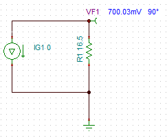
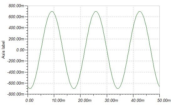
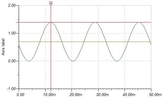
The ideal burden resistor is 16.49Ω, we will use the standard 16.5Ω value for this specific application.  We now have a basic circuit as shown in figure below.  Simulation was ran through Texas Intruments' TINA-TI Spice based program.


imageimage


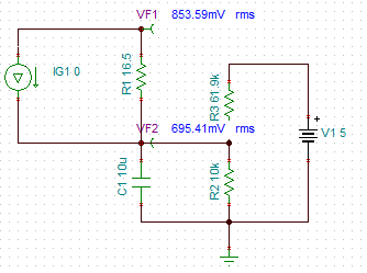
Remember that the voltage signal across the burden resistor is still AC (see right image above), and the ADC is not capable of measuring negative voltage.  So we have to add this AC voltage by 0.7V to make the voltage measurable between 0 and 1.4V.  This can be achieved by adding a clamping circuit as shown below.  The resistor values where calculated using the voltage divider equation to achieve 0.7V across R2 set at 10kΩ.


imageimage

This completes the electronic design part of the power meter.


For the software, we will be porting EmonLib an Arduino Library from openenergymonitor.org to a more portable C library.  Using the ported library, we can calculate the apparent power.  With the apparent power now known we can average the samples over a period of a second to resolve energy in Watt-sec which will determine the carbon footprint usage where 1KWh = 1.52 lbs CO2 (estimated EPA).  Snippet below.


static float aveS = 0;          // average apparent power
static uint32 n = 0;
float Irms = EmonC_CalculateIrms(1480);
float S = Irms * VAC_MAINS;    // S - apparent power, VAC_MAINS 230Vac

WEIGHTED_AVE(&aveS, &n);


if(newSecond)
{
  float co2 = CONVERT_TO_KWH(aveS) * 1.52f;
  DEBUG_LOG("co2: %3.2f\r\n", co2);
  ReportCO2(co2);          // send data to central hub  
  newSecond = false;
}


Update:

Attached partially ported energy monitor library.  Only RMS current calculation is ported atm as there is no hardware support for VI calculation for this project.


Update 2:

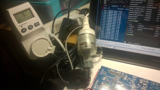
Its just now that I was able to verify this feature.  After some calibration and including the power factor (set at 50%), I got the power usage close enough to match a power meter.  There is a bit of difference but I guess that is caused by the resolution of calculation and that the meter would probably be calculating the actual power factor as well.  Anyways, I think its good enough for now. image


image


Next posts will be about the enclosure, installation and actual testing.


References:

Current monitoring with non-invasive sensor and arduino | Homautomation

How to build an arduino energy monitor - measuring current only | OpenEnergyMonitor

1 kilowatt-hour · BlueSkyModel


Attachments:
EmonLibC.zip
  • Sign in to reply

Top Comments

  • mcb1
    mcb1 over 10 years ago +1
    Christever Your CT transformer does indeed allow measuring of mains voltages BUT care needs to be exercised to ensure it is safe. When these devices are mounted inside a switchboard, the secondary side…
Parents
  • mcb1
    mcb1 over 10 years ago

    Christever

    Your CT transformer does indeed allow measuring of mains voltages BUT care needs to be exercised to ensure it is safe.


    When these devices are mounted inside a switchboard, the secondary side wire is still inside the switchboard and is not usually rated for mains voltages.

    It requires a mains rated sleeve or another method to ensure users aren't potentially exposed to hazardous voltages.


    I detailed one method here and discussed some of the pitfalls.

    Forget Me Not :  eLDERmon  Electrical


    Rather than a physical network connection a WIFI or RF connection is probably the safest way to get the data out and keep everything inside and away from contact.


    Mark

    • Cancel
    • Vote Up +1 Vote Down
    • Sign in to reply
    • More
    • Cancel
Comment
  • mcb1
    mcb1 over 10 years ago

    Christever

    Your CT transformer does indeed allow measuring of mains voltages BUT care needs to be exercised to ensure it is safe.


    When these devices are mounted inside a switchboard, the secondary side wire is still inside the switchboard and is not usually rated for mains voltages.

    It requires a mains rated sleeve or another method to ensure users aren't potentially exposed to hazardous voltages.


    I detailed one method here and discussed some of the pitfalls.

    Forget Me Not :  eLDERmon  Electrical


    Rather than a physical network connection a WIFI or RF connection is probably the safest way to get the data out and keep everything inside and away from contact.


    Mark

    • Cancel
    • Vote Up +1 Vote Down
    • Sign in to reply
    • More
    • Cancel
Children
  • xever
    xever over 10 years ago in reply to mcb1

    Thanks Mark, will surely be following your tips and updating this post once I get the CT sensor fitted.  Although I am planning to make a plastic enclosure for it and will be installing it in the meter box, so it should *theoretically* be not exposing hazardous voltages.  I will still follow some of the guidelines you've mentioned, i.e. 50mm clearance.


    Data will be transmitted over WiFi using the CC3200 Launchpad XL.


    Again, thanks commenting and highlighting the safety aspects of such project.


    Kind regards,


    CdR

    • Cancel
    • Vote Up 0 Vote Down
    • Sign in to reply
    • More
    • Cancel
  • mcb1
    mcb1 over 10 years ago in reply to xever

    xever

    Christever

    The 50mm spacing won't help inside a switchboard ...(it's not possible)

    This option is proabably one method BUT the secondary lead from the sensor needs to be in mains rated sleeve where it exits the switchboard and enters the plastic box.

    You can then use WIFI or RF through the plastic box.image


    image


    It's all about maintaining double insulation ....


    Mark

    • Cancel
    • Vote Up 0 Vote Down
    • Sign in to reply
    • More
    • Cancel
element14 Community

element14 is the first online community specifically for engineers. Connect with your peers and get expert answers to your questions.

  • Members
  • Learn
  • Technologies
  • Challenges & Projects
  • Products
  • Store
  • About Us
  • Feedback & Support
  • FAQs
  • Terms of Use
  • Privacy Policy
  • Legal and Copyright Notices
  • Sitemap
  • Cookies

An Avnet Company © 2025 Premier Farnell Limited. All Rights Reserved.

Premier Farnell Ltd, registered in England and Wales (no 00876412), registered office: Farnell House, Forge Lane, Leeds LS12 2NE.

ICP 备案号 10220084.

Follow element14

  • X
  • Facebook
  • linkedin
  • YouTube