


Inductors
Previous Posts
In The Air: Epidose 1: Introduction
In The Air: Episode 2 - Preparing for Surface Mount Work
In The Air: Episode 3 - Surface Mount Beginnings
Update
I'm designing my circuit board as a booster pack for the CC3200 Launchpad. It's taking a long time because I'm trying to use TI parts for every component, and the plague (read flu) just passed through my household. I'll be finishing the board and ordering it and my parts soon. While waiting for the parts, I will work on the software.
Introduction
Hope on over to Newark or Digikey and do a parametric search for inductors. Ever notice voltage isn't usually a parameter to be refined? It’s always seems to be current for an inductor, voltage for a capacitor, and power for a resistor. This isn't always true, but it is in most instances. Why, do you suppose, are inductors usually current rated and not voltage? I’m going to leave this question unanswered so as to spark a conversation about it.
We were sent four kits as part of the design challenge:
- WE-SPC SMD Shielded Power Inductor http://katalog.we-online.de/en/pbs/7440894?sid=8156c494ef
- WE-MAPI – Metal Alloy Power Inductorhttp://katalog.we-online.de/en/pbs/7443831?sid=8156c494ef
- WE-MAPI - Metal Allow Power Inductor http://katalog.we-online.de/en/pbs/7443833?sid=8156c494ef
- WE-LMHI – SMD Low Profile High Current Molded Inductor http://katalog.we-online.de/en/pbs/7443732?sid=8156c494ef
I hope you didn’t throw the boxes away, because there is a pair of plastic tweezers embedded into the wall of each cardboard box, just in case you didn’t have a pair. Note, they’re anti-static plastic tweezers: http://www.amazon.com/Length-Black-Plastic-Anti-static-Tweezer/dp/B00E6O2KMC
I’m not sure how much heat they can take, so I may have to sacrifice a pair to find out. Kudos to WÜRTH ELEKTRONIK. These kits are great. I’m really impressed with the presentation. Wurth definitely met their motto of “more than you expect”.
The Inductors We Have
Let’s have a look at the packages of the inductors we’ve been provided:
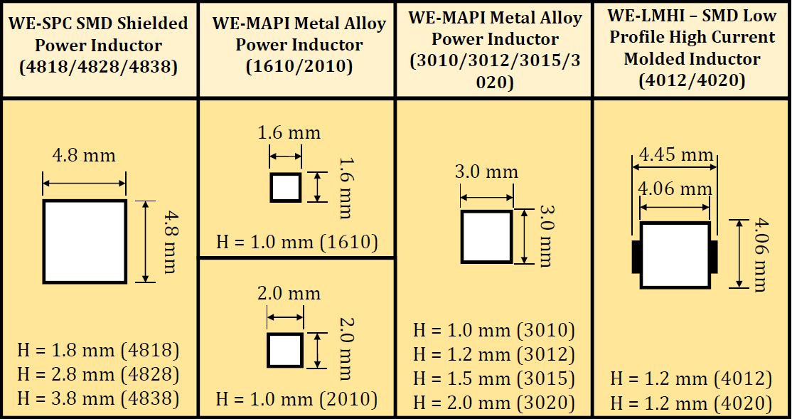
Figure 1: WÜRTH ELEKTRONIK Inductor Selection
This image is my attempt at showing the relative size of each inductor package with respect to each other. The packages are associated with a metric number like 4818. The first two digits refer to the square dimensions of the package (width and length) and the second two digits are the height. For example the 4818 refers to a 4.8 mm square package with a height of 1.8 mm. In Fig 1, notice the first three types (left to right) have the term Power Inductor directly in their names. In fact, all the inductors we have been supplied are power inductors. This is because they are typically used in applications involving power supply design. They have other applications, but by far the most common is likely the design of switching DC to DC voltage converters (think Buck or Boost regulators). The WE-SPC is a coiled power inductor (as far as I can tell) and is shielded. Depending upon your efficiency requirement the presence of a shield can be quite important. It essentially isolates the magnetic field of the inductor from the rest of your circuit. Having said that, it also stops EMI from affecting the rated inductance value. The WE-MAPI inductors are shielded as well and made from a metal alloy, likely proprietary and patented.
If you consider all the MAPI packages they cover the same inductance span as the SPC, but their package is significantly smaller. Let's take a 47 uH SPC and a 47 uH MAPI for comparison.
| Parameteter | 74408941470 (SPC 47 uH) | 74438335470 (MAPI 47 uH) |
|---|---|---|
| Rated Current (A) | 0.4 | 0.4 |
| Saturation Current (A) | 0.75 | 1.2 |
| RDC typical (mΩ) | 960 | 2090 |
| RDC [max?] (A) | 1133 | 2300 |
| Resonant Frequency (MHz) | 14 | 8 |
The first thing that I noticed was, for 47 uH, the MAPI inductor has over twice the DC resistance of the SPC inductors. That's perfectly fine if your application can withstand the I²R losses. I'd go with the MAPI if possible because it is so much smaller and it's 75% the cost of the SPC inductor. Note, in this instance the MAPI is 3.0 mm x 3.0 mm x 1.5 mm and SPC is 4.8 mm x 4.8 mm x 1.8 mm. Personally, I lean more towards price than anything else, so that is what makes the MAPI more attractive to me. The final inductor in our list, the LHMI, is a low profile, high current inductor. It can handle the same or more current than the SPC package, and it's very low profile.The LHMI and SPC cost about the same, so if you need the space you might choose the LHMI. The specifications of the LHMI claim "no acoustic noise and no leakage field", so maybe they are targeted at quiet power supplies for audio equipment? I've heard it mentioned to steer clear of switching regulators for audio applications, but that was back when the switching frequencies were in the tens of kilohertz. I think I will be using the MAPI inductors, because they offer the best performance for the price.
Using the Inductors
Let's assume, like me, you are designing a PCB for your project. This PCB is going to supply power to all your sensors and allow the sensor outputs to be digitized by one of your launch pads. I need to drive a pump in my design, so I used TI's WEBENCH software (on their website) to design a 12 Volt to 3.3 Volt regulator using the TPS62175. If you've never tried the WEBENCH Designer, it's pretty neat. On TI's website if you are looking at the "main page" for a part on the right side will be a link to open the WEBENCH designer for that part. Figure 2 shows the resulting regulator design.
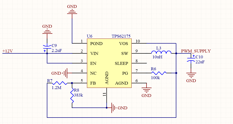
Figure 2: TPS62175 12V to 3.3 Volt Regulator Design from Web Bench.
You'll likely notice the inductor L3, which I chose as a 10 uH MAPI inducutor (P/N: 74438336100). You might also be wondering why there is a pin 11. That's the thermal pad on the underside of the chip. There are other ways to include that pin in the design, I just prefer to add an extra pin. That covers the regulator. Next we'll talk about an extremely important concept with regard to mixed-signal design, that is designs including both an analog and digital ground. Supply and ground decoupling. To emphasize why, let's look at Figure 3.
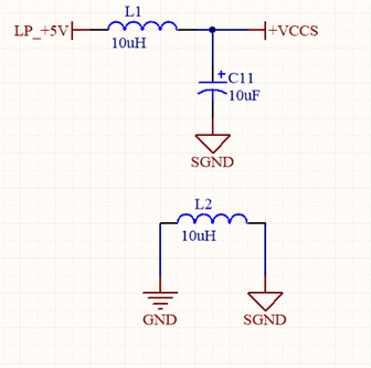
Figure 3: Supply Decoupling (SGND is signal or analog ground)
Figure 3 shows the launch pad designators on the left (GND and LP_+5V) and my decoupled versions on the right (SGND and VCCS). I've decoupled the 5 Volts and ground from the launch pad header connector. Digital circuits are noisy; that's just the way things are. Digital by nature has higher noise immunity, so it stands to reason that the circuitry is likely noisier than its analog counterpart. I don't want any of that noise created by the digital circuitry to show up in my analog circuits (sensors). The easiest way for this noise to get to the analog parts is via the power supply or the ground connection. Given that, we separate them using inductors because our DC signal can pass unaltered and the AC signals (noise) will be presented with a high impedance. Remember the reactance of an inductor is proportional to frequency (X = jωL). This is where the term choke comes from, since AC signals will be attenuated. There are caveats here, especially with the ground decoupling, but unless you are dealing with high return currents it's a pretty safe practice. The issue that could arise is ground lifting. If the return current from the signal or analog ground is high enough the I²R loss of the inductor will lift the analog ground above digital ground. This will likely cause an offset error in your digitized sensor reading.
That's it for now, hope it helps. If you find a mistake, let me know in the comments so I can correct it.


