element14 Community
element14 Community
    Register Log In
  • Site
  • Search
  • Log In Register
  • Members
    Members
    • Benefits of Membership
    • Achievement Levels
    • Members Area
    • Personal Blogs
    • Feedback and Support
    • What's New on element14
  • Learn
    Learn
    • Learning Center
    • eBooks
    • STEM Academy
    • Webinars, Training and Events
    • More
  • Technologies
    Technologies
    • 3D Printing
    • FPGA
    • Industrial Automation
    • Internet of Things
    • Power & Energy
    • Sensors
    • More
  • Challenges & Projects
    Challenges & Projects
    • Design Challenges
    • element14 presents
    • Project14
    • Arduino Projects
    • Raspberry Pi Projects
    • More
  • Products
    Products
    • Arduino
    • Dev Tools
    • Manufacturers
    • Raspberry Pi
    • RoadTests & Reviews
    • Avnet Boards Community
    • More
  • Store
    Store
    • Visit Your Store
    • Choose Another Store
      • Europe
      •  Austria (German)
      •  Belgium (Dutch, French)
      •  Bulgaria (Bulgarian)
      •  Czech Republic (Czech)
      •  Denmark (Danish)
      •  Estonia (Estonian)
      •  Finland (Finnish)
      •  France (French)
      •  Germany (German)
      •  Hungary (Hungarian)
      •  Ireland
      •  Israel
      •  Italy (Italian)
      •  Latvia (Latvian)
      •  
      •  Lithuania (Lithuanian)
      •  Netherlands (Dutch)
      •  Norway (Norwegian)
      •  Poland (Polish)
      •  Portugal (Portuguese)
      •  Romania (Romanian)
      •  Russia (Russian)
      •  Slovakia (Slovak)
      •  Slovenia (Slovenian)
      •  Spain (Spanish)
      •  Sweden (Swedish)
      •  Switzerland(German, French)
      •  Turkey (Turkish)
      •  United Kingdom
      • Asia Pacific
      •  Australia
      •  China
      •  Hong Kong
      •  India
      •  Korea (Korean)
      •  Malaysia
      •  New Zealand
      •  Philippines
      •  Singapore
      •  Taiwan
      •  Thailand (Thai)
      • Americas
      •  Brazil (Portuguese)
      •  Canada
      •  Mexico (Spanish)
      •  United States
      Can't find the country/region you're looking for? Visit our export site or find a local distributor.
  • Translate
  • Profile
IoT on Wheels Design Challenge
  • Challenges & Projects
  • Design Challenges
  • IoT on Wheels Design Challenge
  • More
  • Cancel
IoT on Wheels Design Challenge
Blog IOT on Wheels Design Challenge - Smart Drive - Exploring MEMS board X-NUCLEO-IKS01A2 with Unicleo-GUI - Blog #3
  • Blog
  • Forum
  • Documents
  • Events
  • Mentions
  • Sub-Groups
  • Tags
  • More
  • Cancel
  • New
Blog Post Actions
  • Subscribe by email
  • More
  • Cancel
  • Share
  • Subscribe by email
  • More
  • Cancel
Group Actions
  • Group RSS
  • More
  • Cancel
Engagement
  • Author Author: vlasov01
  • Date Created: 11 Oct 2017 2:40 AM Date Created
  • Views 156 views
  • Likes 4 likes
  • Comments 4 comments
  • unicleo-gui
  • standalone data logging
  • x-nucleo-iks01a2
  • x-cube-mems1
  • data visualization
  • mbed-os
  • smartdrive
Related
Recommended

IOT on Wheels Design Challenge - Smart Drive - Exploring MEMS board X-NUCLEO-IKS01A2 with Unicleo-GUI - Blog #3

vlasov01
vlasov01
11 Oct 2017

IOT on Wheels Design Challenge - Smart Drive - Project Index

Fall Detection with  X-NUCLEO-IKS01A2X-NUCLEO-IKS01A2


This is my 3rd blog post for the "IoT on Wheels Design Challenge. I've explored MQTT connectivity from the STM32L476RG Nucleo board using mbed cloud environment in my previous blogIOT on Wheels Design Challenge - Smart Drive - First Steps with mbed os - Blog #2post.


There are several type of events I'd like to detect from the MCU and its sensors in my project One of them is Fall Detected event I was very happy to discover that mbed has MultiEventIKS01A2 demo application It demonstrates capabilities of different  X-NUCLEO-IKS01A2X-NUCLEO-IKS01A2 sensors including Free Fall Detection

I've compiled it and was able to run successfully on my board.


Standalone Data Logging

We are frequently taking Internet connectivity for granted. It not necessary the case everywhere in the world, and definitely may be limited or absent on the roads. As result I decided to look how can I store data on the board as it has some flash. I was not able to find examples of standalone data logging for STM32 family on mbed. It seems mbed OS 5 doesn't provide the same easy way to access persistent memory as I've got used to on popular x86 or ARM based Linux boards.

Then I've read documentation on X-CUBE-MEMS1 package for  X-NUCLEO-IKS01A2X-NUCLEO-IKS01A2 expansion board on a  NUCLEO-F401RENUCLEO-F401RE or  NUCLEO-L476RGNUCLEO-L476RG development boards It as well comes with MotionFD fall detection library which receives the data acquired from the accelerometer and

pressure sensor to detect fall event; it features:

  • possibility to distinguish whether the user fall occurred or not
  • recognition based only on accelerometer and pressure sensor data
  • required accelerometer and pressure sensor data sampling frequency is 25 Hz
  • occupies 2.4kByte of code memory and 3.4kByte of data memory

But the most interesting for me feature was standalone data logging. It is using the flash sector dedicated to data storage (128 KB), allowing memorization of more than 16,000 data sets.

Data Visualization

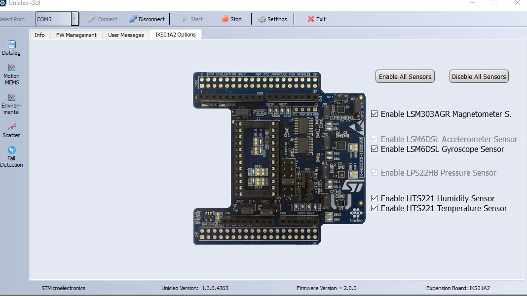
The documentation for X-CUBE-MEMS1 describes use of Unicleo-GUI to visualize in real-time data captured from the board/sensors. I've compiled and loaded Fall Detection application form  X-CUBE-MEMS1 to the board. Unicleo-GUI was able to recognize my board.

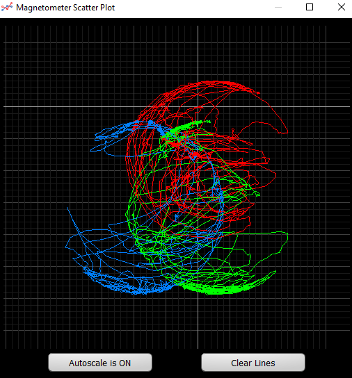
It provides different visualization tools for different sensor types. The following one was for magnetometer:

There is one for environment:

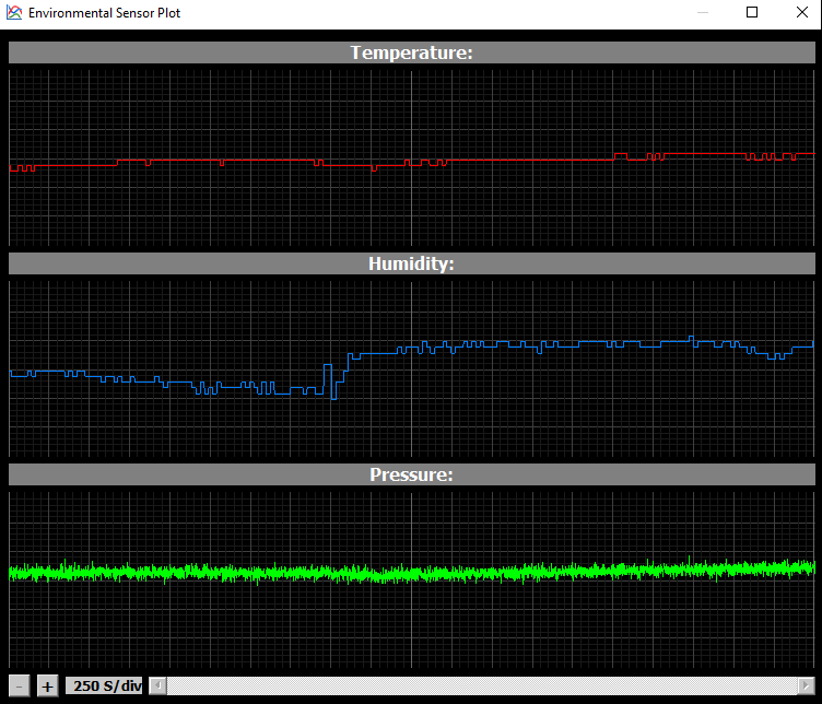
I was a bit surprised by humidity sensor as it fluctuated a lot without any changes in the environment other then my attempts to emulate falls..

There is another visualization tool for motion sensors:

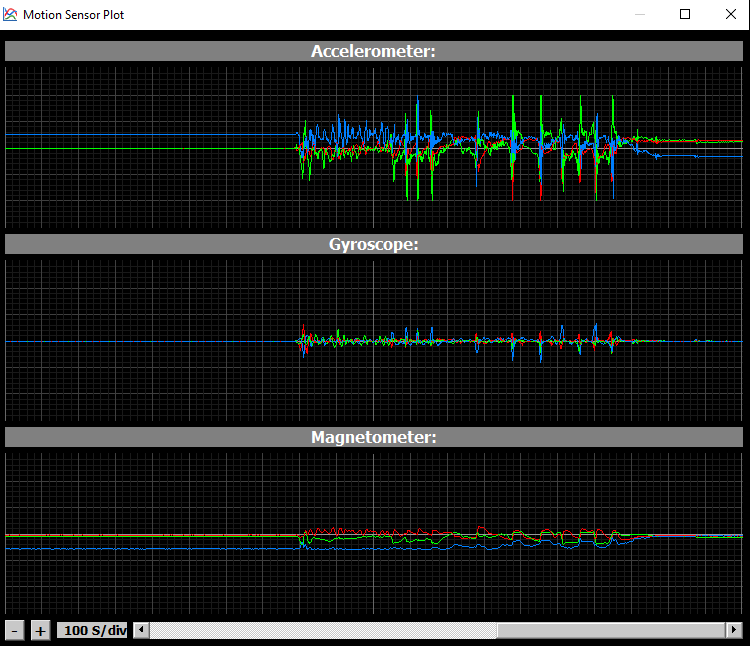
You can see there some large green spikes at times when I was trying to test falls. Unicleo-GUI has as well a GUI for fall detection:

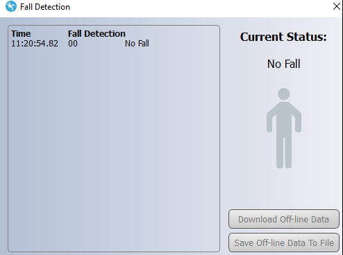
But for some reason it hasn't detected falls compare to mbed sample, which was able to detect them quite reliably.


In addition Unicleo-GUI allows to record all sensor reading in CSV format, so  they can be analyzed to tune parameters of the algorithms.


References

I've found the following STM User Manuals very useful in my exploration:

UM2275, Getting started with MotionFD real-time fall detection library in XCUBE-MEMS1 expansion for STM32Cube

UM1859, Getting started with the X-CUBE-MEMS1 motion MEMS and environmental sensor software expansion for STM32Cube

UM2128, Getting started with Unicleo-GUI for motion MEMS and environmental sensor software expansion for STM32Cube

Anonymous

Top Comments

  • e14phil
    e14phil over 4 years ago +1

    Does anyone have any insight as to what the magnetometer is showing with the 3 colored spheres, It looks great but I have no idea what I am looking at haha

  • vlasov01
    vlasov01 over 4 years ago in reply to e14phil +1

    This is a description of the magnetometer visualization from UM2128 http://www.st.com/content/ccc/resource/technical/document/user_manual/group0/b9/d0/7c/c5/a8/55/4c/bc/DM00337036/files/DM00337036.pdf…

  • janousv@stm
    janousv@stm over 4 years ago in reply to vlasov01

    just to add, .... when you start to rotate with the board hosting magnetometer in the 3D space - in all possible directions - and you capture the magnetometer raw data at the same time, as a result, you will get the Earth magnetic field exposed to all 3 magnetometer axis with a different strength depending on the actual orientation of the sensor vs. the Earth magnetic field. In 2D plots you can see this as filled circles. Interesting is to notice, that the 2D filled circles are shifted from the center of the coordinates, which means there is an offset in the measurement. For practical use of the magnetometer, it is needed to calibrate the sensor on offset.

    • Cancel
    • Up 0 Down
    • Reply
    • More
    • Cancel
  • DAB
    DAB over 4 years ago

    Very interesting results.


    DAB

    • Cancel
    • Up 0 Down
    • Reply
    • More
    • Cancel
  • vlasov01
    vlasov01 over 4 years ago in reply to e14phil

    This is a description of the magnetometer visualization from UM2128 http://www.st.com/content/ccc/resource/technical/document/user_manual/group0/b9/d0/7c/c5/a8/55/4c/bc/DM00337036/files/DM00337036.pdf/jcr:content/translations/en.DM00337036.pdf :

    • the red line represents the magnetometer X data on the X-axis, and the magnetometer Y-data on the Y-axis;
    • the green line represents the magnetometer X data on the X-axis, and the magnetometer Z-data on the Y-axis;
    • the blue line represents the magnetometer Y data on the X-axis, and the magnetometer Z-data on the Y-axis.
    • Cancel
    • Up +1 Down
    • Reply
    • More
    • Cancel
  • e14phil
    e14phil over 4 years ago

    Does anyone have any insight as to what the magnetometer is showing with the 3 colored spheres, It looks great but I have no idea what I am looking at haha

    • Cancel
    • Up +1 Down
    • Reply
    • More
    • Cancel
Element14

element14 is the first online community specifically for engineers. Connect with your peers and get expert answers to your questions.

  • Members
  • Learn
  • Technologies
  • Challenges & Projects
  • Products
  • Store
  • About Us
  • Feedback & Support
  • FAQs
  • Terms of Use
  • Privacy Policy
  • Legal and Copyright Notices
  • Sitemap
  • Cookies

An Avnet Company © 2022 Premier Farnell Limited. All Rights Reserved.

Premier Farnell Ltd, registered in England and Wales (no 00876412), registered office: Farnell House, Forge Lane, Leeds LS12 2NE.

ICP 备案号 10220084.

Follow element14

  • Facebook
  • Twitter
  • linkedin
  • YouTube