element14 Community
element14 Community
    Register Log In
  • Site
  • Search
  • Log In Register
  • About Us
  • Community Hub
    Community Hub
    • What's New on element14
    • Feedback and Support
    • Benefits of Membership
    • Personal Blogs
    • Members Area
    • Achievement Levels
  • Learn
    Learn
    • Ask an Expert
    • eBooks
    • element14 presents
    • Learning Center
    • Tech Spotlight
    • STEM Academy
    • Webinars, Training and Events
    • Learning Groups
  • Technologies
    Technologies
    • 3D Printing
    • FPGA
    • Industrial Automation
    • Internet of Things
    • Power & Energy
    • Sensors
    • Technology Groups
  • Challenges & Projects
    Challenges & Projects
    • Design Challenges
    • element14 presents Projects
    • Project14
    • Arduino Projects
    • Raspberry Pi Projects
    • Project Groups
  • Products
    Products
    • Arduino
    • Avnet Boards Community
    • Dev Tools
    • Manufacturers
    • Multicomp Pro
    • Product Groups
    • Raspberry Pi
    • RoadTests & Reviews
  • Store
    Store
    • Visit Your Store
    • Choose another store...
      • Europe
      •  Austria (German)
      •  Belgium (Dutch, French)
      •  Bulgaria (Bulgarian)
      •  Czech Republic (Czech)
      •  Denmark (Danish)
      •  Estonia (Estonian)
      •  Finland (Finnish)
      •  France (French)
      •  Germany (German)
      •  Hungary (Hungarian)
      •  Ireland
      •  Israel
      •  Italy (Italian)
      •  Latvia (Latvian)
      •  
      •  Lithuania (Lithuanian)
      •  Netherlands (Dutch)
      •  Norway (Norwegian)
      •  Poland (Polish)
      •  Portugal (Portuguese)
      •  Romania (Romanian)
      •  Russia (Russian)
      •  Slovakia (Slovak)
      •  Slovenia (Slovenian)
      •  Spain (Spanish)
      •  Sweden (Swedish)
      •  Switzerland(German, French)
      •  Turkey (Turkish)
      •  United Kingdom
      • Asia Pacific
      •  Australia
      •  China
      •  Hong Kong
      •  India
      •  Korea (Korean)
      •  Malaysia
      •  New Zealand
      •  Philippines
      •  Singapore
      •  Taiwan
      •  Thailand (Thai)
      • Americas
      •  Brazil (Portuguese)
      •  Canada
      •  Mexico (Spanish)
      •  United States
      Can't find the country/region you're looking for? Visit our export site or find a local distributor.
  • Translate
  • Profile
  • Settings
IoT on Wheels Design Challenge
  • Challenges & Projects
  • Design Challenges
  • IoT on Wheels Design Challenge
  • More
  • Cancel
IoT on Wheels Design Challenge
Blog The Konker Connection - Blog 2
  • Blog
  • Forum
  • Documents
  • Polls
  • Files
  • Events
  • Mentions
  • Sub-Groups
  • Tags
  • More
  • Cancel
  • New
  • Share
  • More
  • Cancel
Group Actions
  • Group RSS
  • More
  • Cancel
Engagement
  • Author Author: dougw
  • Date Created: 28 Sep 2017 4:17 AM Date Created
  • Views 825 views
  • Likes 9 likes
  • Comments 4 comments
  • iot on wheels design challenge
  • doug wong
  • iot on wheels
  • konker
Related
Recommended

The Konker Connection - Blog 2

dougw
dougw
28 Sep 2017

My first tasks are to get the long lead activities under way. This includes designing a Nucleo Expansion PCB for the LCD and ordering parts. I actually started ordering parts as soon as I was announced as a participant, so I was able to unbox the I-NUCLEO-LRWAN1 module at the same time as the sponsored design kit.

To design the Nucleo expansion card I need to map out which pins on the MCU card will be used by each peripheral card. All of the expansion cards supplied with the kit only use arduino connectors, which doesn't seem optimal to me. I would have thought Nucleo expansion cards should use the Morpho connectors so they have control over the number of pin conflicts and leaving the arduino connectors available for arduino shields. As it is, the 3 expansion cards supplied with the kit take up the vast majority of arduino pins, making it pretty unlikely that another arduino shield can be used. Even amongst the 3 Nucleo expansion cards there are about 10 pins that overlap. It may be possible to resolve these conflicts as some pin assignments look like they can be altered with jumpers, but I have to fit a fourth Nucleo expansion (I-NUCLEO-LRWAN1) card onto the stack and it also uses only arduino pins. The Wi-Fi Expansion card alone connects to 23 of the 32 arduino pins.

Right now I have a major problem with the I-NUCLEO-LRWAN1 card because I cannot find out which pins it uses - there just doesn't seem to be any documentation on this. So this PCB design effort is semi-stalled until I can dig up more complete documentation. It is going to be painful and risky if I have to reverse engineer the LoRa card to discover its pinout.

Of course there are plenty of other things to do. One of them is to research whether it is feasible to measure fuel levels from outside the gas tank without tapping into the fuel plumbing or opening the tank. I will try to do this by measuring the resonant frequency of the air in the tank. The following video is a first attempt using a 2 liter bottle with water instead of gasoline.

You don't have permission to edit metadata of this video.
Edit media
x
image
Upload Preview
image

I had to split the video to get it to upload...

You don't have permission to edit metadata of this video.
Edit media
x
image
Upload Preview
image

The Rohde & Schwarz RTB2004 oscilloscope did a spectacular job of supplying both the excitation and the measurements for my tests. I literally did not have to build anything.

It clearly shows some well defined resonances that change pitch as the water level changes. However, my first look at the data yields very confusing relationships. The only thing that is clear at this point is that it is going to take lots of work to get the results I want.

Here is a scatter plot of resonant frequencies on the X axis versus air volume on the Y axis:

image
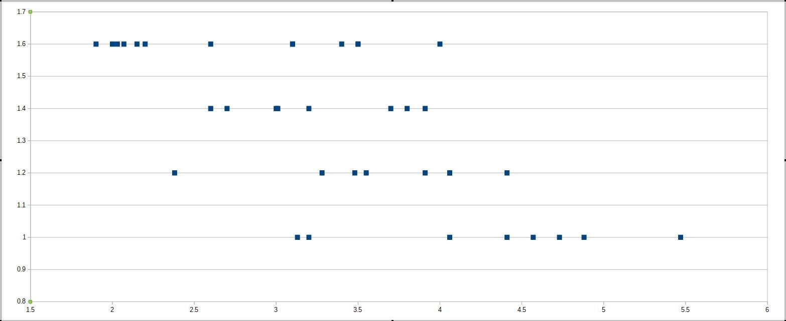
There doesn't seem to be much vertical alignment (indicating resonances that do not change with volume)

Below I assume the frequency increases linearly as the air volume decreases and draw some straight lines through possibly related resonances:

image

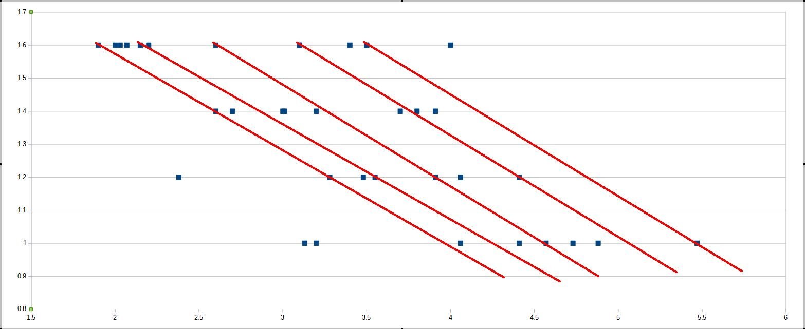
It doesn't make sense to me that all the frequencies would increase with decreasing volume, but maybe it is possible.

Next I tried to add water slowly and track the resonant frequency of a single initial resonance to see if these straight lines represent what is really going on.

This was a bit harder than I anticipated. It seems like a resonance dies off as volume changes by about 30 ml and a new resonance mode starts up at a different frequency. This may mean most of these resonances are not the air cavity, but the varying mass relationships can allow whatever is vibrating to resonate or it can damp them out. So I will need to investigate every resonance to see if it actually tracks the air volume ..... oh joy. At least this cool oscilloscope allows me to investigate without rebuilding a bunch of circuitry. I was hoping that the lowest resonance would be the Helmholtz resonance, but so far the data doesn't support this theory. (The Helmholtz resonance is the lowest resonance of the air in a cavity) Some people do a whole 2 year thesis on stuff like this - I need results faster than that.

One thing I didn't plot above is the amplitude of the resonant frequencies, but it seems to have some correlation with volume - the more water the higher the signal amplitude.

The investigation continues....


Project Links:

IoT On Wheels Design Challenge page


Links to other blogs on this project are included in the first blog:

https://www.element14.com/community/community/design-challenges/iot-on-wheels/blog/2017/09/21/the-konker-connection-blog-1


  • Sign in to reply

Top Comments

  • mcb1
    mcb1 over 7 years ago +1
    Interesting challenge ... One thing you may wish to check first is if the tank staddles the chassis backbone. If it does you'll have two almost sperate chambers at lower fuel levels, and then you've got…
  • dougw
    dougw over 7 years ago in reply to mcb1 +1
    Good points. The tank is a saddle bag type as almost all are, and it will definitely complicate the measurement. I may end up having to use a more conventional sensor, but I'm going to have some fun exploring…
  • jc2048
    jc2048 over 7 years ago +1
    Fascinating experiment. I'm not very clear what's going on. As I understand it, if you have a musical instrument like a guitar or violin then much of the energy gets to the back surface via the sound post…
  • dougw
    dougw over 7 years ago in reply to jc2048

    I'm sure you are right all those resonant modes are present. The air in the cavity will also have a resonance which may be smaller energy/amplitude since sound travels better in solid materials and that is where the excitation originates. If you blow across the top of the bottle you can hear a resonance, which give some idea of the air resonance and the pitch changes with fluid level, but the bottle material is still in the mix. I was hoping (without doing any math) that the air resonances would be quite different from the solid material resonances. However if they change with fluid level, I'm okay with measuring them instead.

    Trying the water outside is an interesting idea, the air resonance may be the most constant one as the bottle gets dunked, but it introduces an outer container to contend with.

    I was planning to see if I could get some useful data from the FFT, although my first try with other waveforms resulted in a very confusing mess. I don't think my excitation transducer does a good job of transferring other wave forms to the bottle. For example square waves end up looking mainly like positive and negative spikes at the waveform transitions.

    Resonances are easy to find and see, but it is hard to see how they change with fluid level, because it is hard to smoothly change the water level in my rig. I may try a tube feed to get around this.

    • Cancel
    • Vote Up +1 Vote Down
    • Sign in to reply
    • More
    • Cancel
  • jc2048
    jc2048 over 7 years ago

    Fascinating experiment.


    I'm not very clear what's going on. As I understand it, if you have a musical instrument like a guitar or violin then much of the energy gets to the back surface via the sound post and not through the air of the cavity (but I'm in no way an expert in this, so take this as vaguely remembered stuff from reading about musical acoustics in the past). So I would think that here the energy transfer is much more efficient through the plastic material (as well as being much faster). That might suggest that you're looking at the superposition of all the multiple paths through the plastic. Those paths would vary because the boundary between water (which will damp oscillations) and air is effectively an impedance change and you'd get reflections off of it, but the relationships would be complicated because it's a 2-D structure.


    One way to experiment with that and see if it has any merit at all would be to put the water on the outside rather than the inside and see if you got a similar effect.


    Another experiment would be to try something other than a sinewave.


    Isn't it possible to drive the transducer with a signal that has a continuous spectrum so you could look at the result varying in real time on the FFT plot rather than having to manually plot the resonances?

    • Cancel
    • Vote Up +1 Vote Down
    • Sign in to reply
    • More
    • Cancel
  • dougw
    dougw over 7 years ago in reply to mcb1

    Good points. The tank is a saddle bag type as almost all are, and it will definitely complicate the measurement. I may end up having to use a more conventional sensor, but I'm going to have some fun exploring this method and learning about acoustic resonance until I'm sure this method isn't feasible for this project. I'm spending quite a bit of time on this right now because you can't achieve a tough goal like this without  going hard at it. I was thinking I might need a lock-in amplifier or a synchronous demodulator, but the signals are really clean. There is just a lot of complexity in resonant modes that needs to be deciphered.

    • Cancel
    • Vote Up +1 Vote Down
    • Sign in to reply
    • More
    • Cancel
  • mcb1
    mcb1 over 7 years ago

    Interesting challenge ...

    One thing you may wish to check first is if the tank staddles the chassis backbone.

    If it does you'll have two almost sperate chambers at lower fuel levels, and then you've got the nonlinear shape to deal with.


    I would imagine it would be easier to fit a flowmeter inline.


    You might need to resort to a simple capacitive sensor mounted to the cap.......


    Mark

    • Cancel
    • Vote Up +1 Vote Down
    • Sign in to reply
    • More
    • Cancel
element14 Community

element14 is the first online community specifically for engineers. Connect with your peers and get expert answers to your questions.

  • Members
  • Learn
  • Technologies
  • Challenges & Projects
  • Products
  • Store
  • About Us
  • Feedback & Support
  • FAQs
  • Terms of Use
  • Privacy Policy
  • Legal and Copyright Notices
  • Sitemap
  • Cookies

An Avnet Company © 2025 Premier Farnell Limited. All Rights Reserved.

Premier Farnell Ltd, registered in England and Wales (no 00876412), registered office: Farnell House, Forge Lane, Leeds LS12 2NE.

ICP 备案号 10220084.

Follow element14

  • X
  • Facebook
  • linkedin
  • YouTube