


![]() BLOG#4 Testing Part 1 (Case Enclosure Reliability Monitor)
BLOG#4 Testing Part 1 (Case Enclosure Reliability Monitor)
Test#2 - Enclosure1554UGY Test Design
This is my 1st Test design to test the reliability of the Hammond Enclosure 1554UGY
The following components are being used::Arduino MKR WAN 1300 with LoRa radio antenna,DS18B20 Temperature Sensor,Mini OLED I2C Display (SSD1306)
A project sponsored by Hammond Manufacturing for the Design Challenge: Just Encase
| <<< PREVIOUS BLOG | NEXT BLOG >>> |
|---|---|
| Blog#5 Testing - Part 2 (Case Enclosure Reliability Monitor) |
Table of Contents
TEST 1 - Measure the Temperature outside of an enclosure
Description
- This simple test design, will measure the temperature outside the 1554UGY enclosure and send the values to a dashboard on the Arduino IoT Cloud
- My original plan was to run the MKR inside the enclosure, powered by batteries. (Refer to Appendix A below where I describe how to run on batteries.)
- But I found out that I needed 5V for the temp sensor circuit, so I reverted to USB power
- Also there needs to be a LoRa antenna connected to MKR to communicate the data to a second LorRa antenna attached to a second MKR. This design is describe in Blog#3..
- I will modify the sketches and dashboard used in Blog#3 to send the temperature data through the design.
Software design
SENDER
- First off I will make modifications to the Sender sketch
- This sketch runs on MKR1
- I added code for a Temp sensor and an OLED display
- DS18B20 Temperature Sensor
- OLED I2C Display (SSD1306)
- The additions to the Basic Sketch are as follows.
- Include the single wire library OneWire.h
- include a function displayValues(float v) to print the value to the OLED
- In SETUP()
- Add configuration code.
- initialize the I2C for the OLED
- in the LOOP()
- Get the temperature value
- put the temp value in to a value pair variable intemp;:<value>
- Call the OLED function to write the temp value
- Send the string in a LoRa packet to the MKR2.
The Wiring Diagram
- This diagram shows how to connect the following components to the MKR WAN 1300.
- DS18B20 Temperature Sensor
- Used to take the current Temperature.
- Mini OLED I2C Display (SSD1306)
- Used to display the current Temperature value before sending it to the LoRa receiver.

THE CODE
|
1-20-2020 Added OLED Adafruit_SSD1306 support. */ // MKRWAN - Version: 1.0.15 #include <SPI.h> #include <OneWire.h> // Include Adafruit Graphics & OLED libraries #define ONE_WIRE_BUS 2 OneWire oneWire(ONE_WIRE_BUS); DallasTemperature sensors (&oneWire); float temperature= 0.0; // OLED CODE for MKR WAN 1300 void setup() { Serial.println("LoRa Sender"); if (!LoRa.begin(915E6)) { // oled dispaly tempreture void loop() { // send packet //getting temperature temperature = sensors.getTempCByIndex(0); // VALUE RETURNED IN cELCIUS // display the temp on OLED delay(5000); |
RECEIVER
- No changes to this sketch, Which runs on MKR2
- It's a passthrough sketch to relay the Telemetry Data send by the MRK1
- I did add some OLED code to it
The Wiring Diagram
- Showing the MKR WAN 1300 with a LoRa Antenna connected via a serial connection to the Nano 33 IoT

THE CODE
|
/* */ #include <SPI.h> // Include Adafruit Graphics & OLED libraries // CODE for MKR WAN 1300 // Declaration for an SSD1306 display connected to I2C (SDA, SCL pins) String inputString = ""; // a String to hold incoming data void setup() { Serial.println("LoRa Receiver"); if (!LoRa.begin((915E6))) { // OLED DISPLAY FUNCTION to display numbers. void loop() { // read packet // display on OLED |
Nano IoT 33 Sketch
- This sketch is generated by the Arduino cloud, when you create a temperature Thing on the Arduino Cloud
- The same code used in the sketch in blog#3 will be modified to add the processing of the temperature
- Serial RX connection for the Packet coming from MKR2
- Break out the value pairs (intemp:<value>) sent from the MKR1
THE CODE
|
/* Arduino IoT Cloud Variables description The following variables are automatically generated and updated when changes are made to the Thing String counter; Variables which are marked as READ/WRITE in the Cloud Thing will also have functions #include "thingProperties.h" float retFloat(String stringOne) { // Defined in thingProperties.h // Connect to Arduino IoT Cloud void loop() { // use the string when a newline arrives:
/* /*
|
Libraries
-
// MKRWAN - Version: 1.0.15
#include <MKRWAN.h> -
#include <SPI.h>
-
#include <LoRa.h>
-
// Include Adafruit Graphics & OLED libraries
#include <Adafruit_GFX.h>
#include <Adafruit_SSD1306.h> - #include <OneWire.h>
#include <DallasTemperature.h>
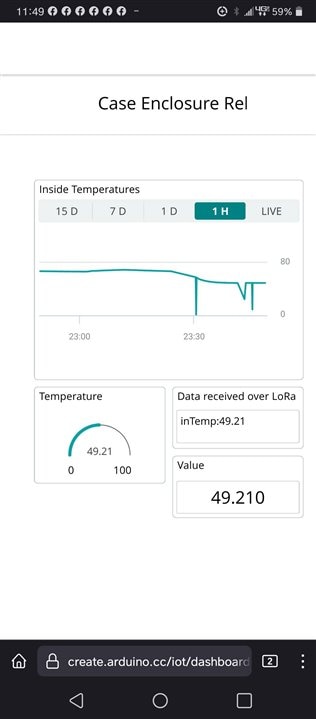
Dashboard GUI Design
- the Dashboard is similar to blog#3 in that it display a value using widgets.
- I uses the device Nano IoT
- For the INSIDE_TEMPRETURE , I created thing for temperature.
- I then created a dashboard with widgets to visualize the temperature.
- Widgets Used:
- The packet received
- Value sent
- Graph the temp
- Gauge of the incoming temps


Running the Test
The Lora sender
Putting the LoRa Sender into an 1554UGY Enclosure
- I placed these components into the enclosure1554UGY
- I'm using 2 Hammond Manufacturing Cable Glands That I placed on the cover of the enclosure
- 1427 CG16 - for the Power USB connector
- 1427 NCGPG7G - for the Temperature Sensor wire.
- The follow pictorial shows how I stuffed the circuit into the 1554UGY and attached the Cable glands to it.
- I then placed the enclosure in several environments to test how the enclosure stood up.
- I placed the Enclosure in my office, garage, outside overnight in the snow and in a 106 degrees.Fahrenheit. and the electronics still continued to operate.
-
First I drilled the holes for the cable glands.
I used the drill bits shown in this picture to drill the holes
on the cover of the enclosure.
I then Attached the cable glands shown.

Then I ran the USB and the sensor cables through the
Cable glands. I stuffed the 3 breadboards into the
Case and connected the sensor cable ends to the
Alligator clips. I then attached the USB cable to the
MKR WAN 1300. The OLED display started to display the current tempreture.
SUCESS!!!!
Next Close it up and plug it in.


Here is an example of using the waterproof Temperature Sensor to
Check out the Water temp in my wife's Beta fish Tank. We just purchased
a heater that is suppose to keep the water at a automatic temp Of 75 degrees Fahrenheit.
Which I was happy it did the job.

- Here are a few pictures of the environments that I subjected the temperature enclosure to
|
II placed it in my garage a few hours |
 |
|
I placed it outside overnight. It was about 27F that night and a dusting of snow fell during the night |
 |
|
In the morning I placed the temp probe into the snowbank |
 |
|
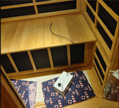
My final test was to place the Enclosure into my personal sauna |
|
|
|
 |
|
Here are the graphs showing the temperature changes as I moved the GRAPH of all environments over 24 hours
|
GRAPH of the time of the enclosure in my sauna
|


The LoRa receiver/CloudUpLoader and The Dashboard
Dashboard on my Phone
Test Conclusions
- Once I implemented the Design outside the enclosure successfully, all the test ran very smoothly
- In the next Blog, I redesigned the Basic design to add different sensors and use the 2nd Enclosure case.
Appendix A - Running the MKRWAN 1300 on Battery power.
- The MKR will run on battery power. I was able to connect a Battery Holder that I purchased on Amazon to the MKRWAN 1300.
- Here is what needs to be done to upload and run sketches under battery power.
- Get a Battery holder with leads

- I purchased a pack of 3 from Amazon
- LAMPVPATH (Pack of 3) 2 AA Battery Holder with Leads
- Type of AA Battery Holder: 2 AA battery holder, 2x 1.5V aa battery holder with wires
- Voltage Output of One Double A Battery Holder: 3V, 2 x 1.5v aa batteries = 3v aa battery holder
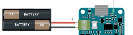
- Connect the battery holder to the MKR WAN 1300
- Connect the Leads from the holder to the GREEN connector on the MKR WAN 1300 as described in pic below.
- DO not insert the AA batteries yet. We need to perform an upload with the serial cable.
- Some Holders I've seen have an on/off switch. THe one I'm using does not.
- Test the Battery Holder
- Use the BLINK example to test thebattery holder connection.
- With the Serial USB cable connected , upload and run the blink example.
- NEXT, disconnect the serial cable and place the 2 AA bateries into the Holder.
- BLINK, should now be running. SUCESS, your running on battery power.
- If the BLINK example does not run then check the following:
- Assure that there is no code that checks for a serial cable,
- check with other batteries
- Make sure the Leads are connected properly.
| <<< PREVIOUS BLOG | NEXT BLOG >>> |
|---|---|
| Blog#5 Testing - Part 2 (Case Enclosure Reliability Monitor) |
|
REFERENCES
|
|---|
| OLED on an MKR |
| 5pcs DS18B20 Temperature Sensor Temperature Probe |
| Enclosure 1554UGY |
| 1427NCGPG7G Cable Gland |
| 1427CG16 Cable Gland |
-

skruglewicz
-
Cancel
-
Vote Up
0
Vote Down
-
-
Sign in to reply
-
More
-
Cancel
Comment-

skruglewicz
-
Cancel
-
Vote Up
0
Vote Down
-
-
Sign in to reply
-
More
-
Cancel
Children