


![]() BLOG#5 Testing Part 2 (Case Enclosure Reliability Monitor)
BLOG#5 Testing Part 2 (Case Enclosure Reliability Monitor)
Test#2 - Enclosure 155H2GYCL Test Design
For this Test, I purchased two Grove Sensors from Seeed and used two of sensors from the supplied Grove starter Kit.
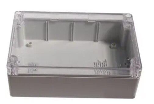
This is my 2nd Test, using a Hammond Enclosure. I will be testing the Ingress Protection Rating: of IP68 on the enclosure model:155H2CYCL.
I also purchased the Arduino MKR Connector Carrier from the Arduino Store, for this test
I'm utilizing the provided Arduino MKR WAN 1300 boards supplied by Hammond Manufacturing for the Design Challenge: Just Encase.
TEST# 2 - Measure the Environment within the Waterproof Enclosure 1554H2GYCL
-
Description
- For this Test, I purchased two Grove Sensors from Seeed and used two of sensors from the supplied Grove starter Kit.
- I also purchased the Arduino MKR Connector Carrier from the Arduino Store. This is used to attach the sender MKR1 from the previous test and attach the groove sensor connectors.
- The List of components used in this test:
- Arduino MKR Connector Carrier
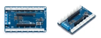
- The Arduino MKR CONNECTOR CARRIER provides Seeed Studio's Grove connectors to your MKR board.
- This shield can allow you to build applications with different IoT connectivity's by simply changing the MKR board and with almost no changes to the code.
- BUY it from the Arduino Store
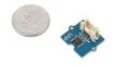
- Grove - Dust Sensor(PPD42NS)SKU 101020012
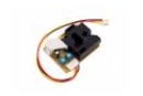
- This Dust Sensor gives a good indication of the air quality in an environment by measuring the dust concentration.
- The Particulate Matter level (PM level) in the air is measured by counting the Low Pulse Occupancy time (LPO time) in a given time unit. LPO time is proportional to PM concentration. This sensor can provide reliable data for air purifier systems; it is responsive to PM of diameter 1μm.
- Buy it from Seeed
- Grove - Water Sensor SKU 101020018
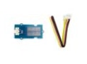
- Grove - Water Sensor detects the presence of water using exposed PCB traces.
- The sensor is made up of interlaced traces of Ground and Sensor signals.
- The sensor traces are weakly pulled up using 1 MΩ resistor.
- The resistor will pull the sensor trace value high until a drop of water shorts the sensor trace to the ground trace.
- USB Ruggedized Charger for Power
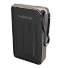
- The AdventureMax 10000mAh by MyCharge
- splash resistant
- drop resistant
- dirt-proof
- II had this charger lying around the house. I decided to use it to power the MKR WAN 1300.
- Grove - Starter Kit Sensors
- Grove - LCD RGB Backlight
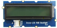
- The Grove - LCD RGB Backlight supports text display, using user-defined characters. It enables you to set the backlight color, using the simple and concise Grove interface. It uses I2C as the communication method with your Arduino.
- This is a 16x2 LCD screen.
- It is capable of displaying two rows of sixteen-character texts, supporting languages such as English and Japanese.
- Grove – Temperature Sensor
 the Grove - Temperature Sensor uses a thermistor which returns the ambient temperature
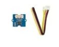 .
.- The board then converts this voltage value measured by an analog input pin to a temperature.
- The operating range is -40 to 125 degrees Celsius.
- Wiki] Grove - Temperature Sensor
- Grove - LCD RGB Backlight
- Arduino MKR Connector Carrier
-
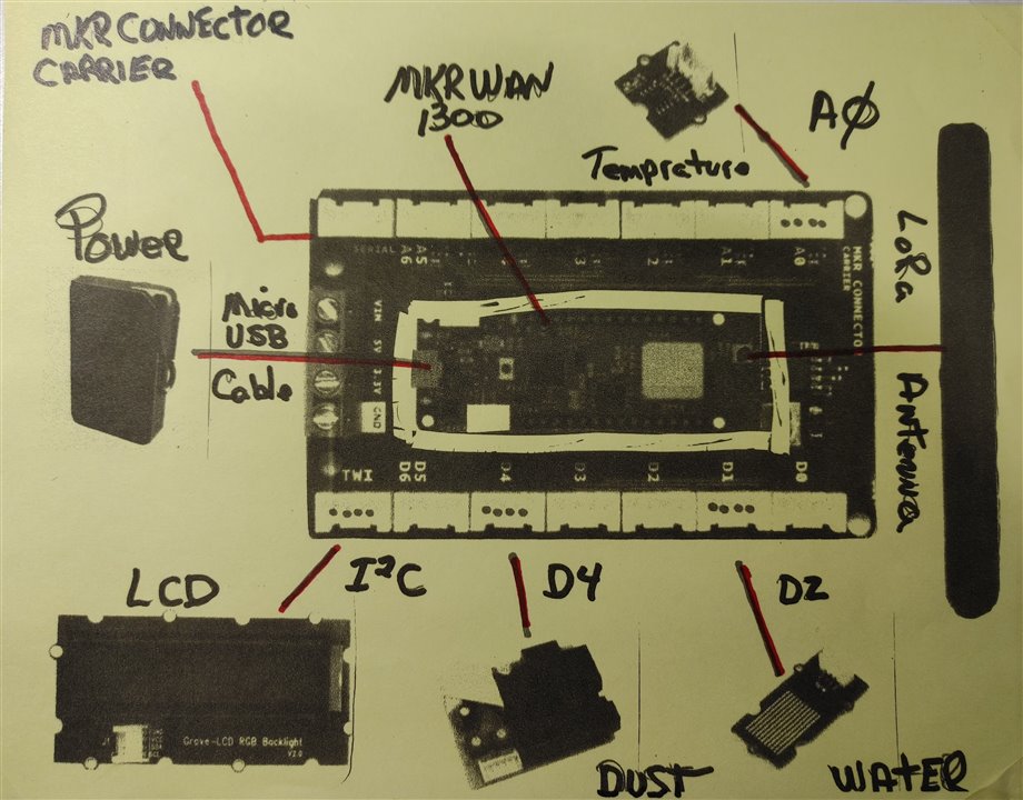
Wiring Diagram
- All the sensors mentioned in the previous section are connected to the Arduino Connector Carrier with a Groove Cable connected to the designated connectors.
- One end of the cable is attached to the Grove sensor and the other to the Grove connector on the Carrier.
- The LCD Display is attached to the TWI ()I2C) connector
- The TEMPRATURE sensor is attached to the analog A0 connector.
- The DUST sensor is attached to the digital D4 connector
- The WATER sensor is attached to the digital D2 connector
- The Arduino MKRWAN 1300 Is attached to the Connector Carrier in the relation shown below
- For POWER, the AdventureMax 10000mAh is attached to the USB connector on the MKRWAN 1300
- The LoRa Antenna is attached to the antenna connector on the MKRWAN 1300
- BLOCK DIGARAM
- Here is a diagram of components:
- THE BUILD
- Carrier Connector and the Attached components
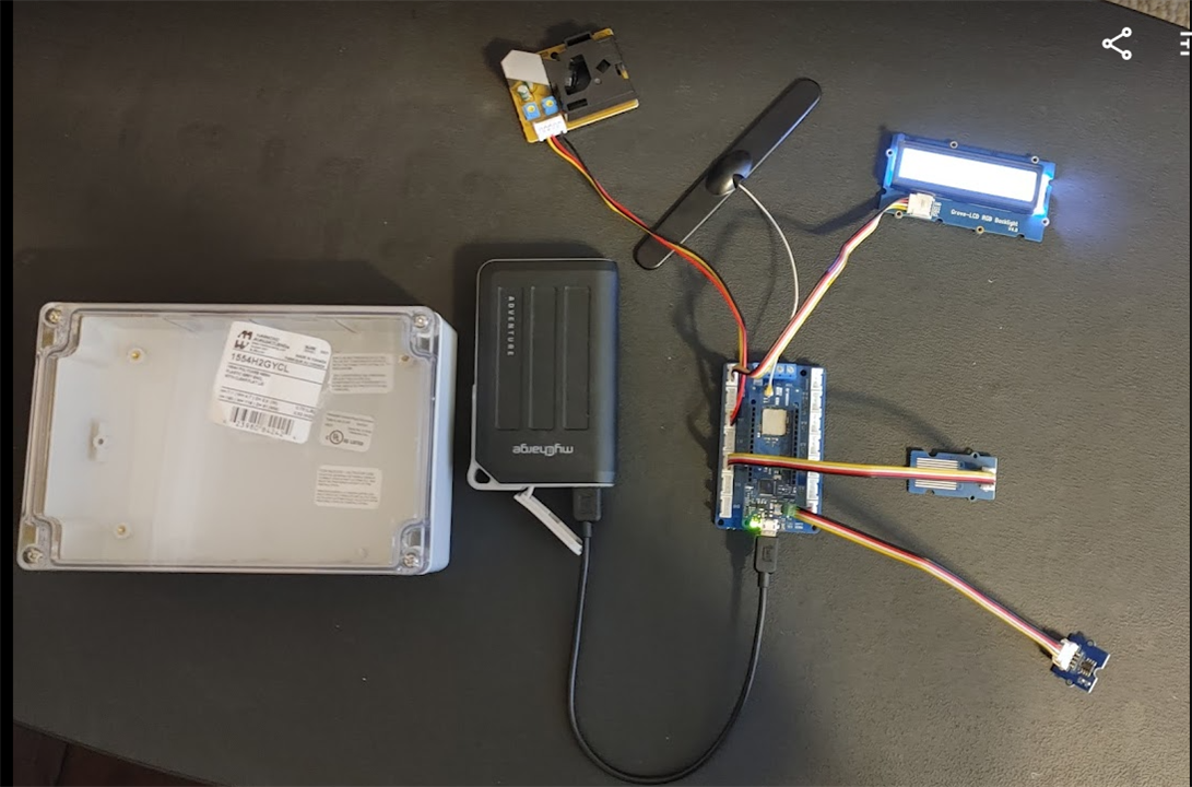
- Carrier Connector and the Attached components
- Here is a diagram of components:
SOFTWARE DESIGN
Libraries
- rgb_lcd.h
- used for the LCD
- README.md
- MKRWAN.h
- used for Lora communications .
- Installed by the Arduino IDE Library Manger
- LoRa.h
- the library used for sending and receiving data using LoRa radios.
- GitHub - sandeepmistry/arduino-LoRa: An Arduino library for sending and receiving data using LoRa radios.
- Wire.h
- This library allows you to communicate with I2C / TWI devices.
- It is needed by the Grove LCD Display
Arduino Sketches
- Three MCU"s, Three Sketches to get the the data through.
- The next Three section will describe the 3 sketches used to get the data thru and onto the Arduino IoT cloud.
LoRa SENDER - MKR_LoRa_Sender_E2.ino on MKR1
- This sketch is Uploaded to the MKR1 board in my design.
- This Sketch, will be used to transmit LoRaWAN packets to the MKR2 LoRa Receiver board.
- As described in the Design section above it will have 3 Grove sensors and 1 Grove LCD display connected to the Arduino MKR Connector Carrier.
- a MKR WN 1300 (MKR1) is attached to the Carrier.
- one by one, each sensor is read.
- after each sensor is read, a LoRa a packet with the sensor value is sent
- In the packet send function the value is displayed on the LCD display.
CODE- MKR_LoRa_Sender_E2.ino
CODE HAS MOVED TO COMMENTS BELOW
LoRa Receiver - MKR_LoRa_Reeiver_UnitTest.ino on MKR2
- This Sketch, will be used to receive LoRaWAN packets.
- It is the same code that I used in Test#1, but I have included here for brevity
- The packets will contain telemetry data that will be sent over a serial line to the Nano 33 IoT.
CODE - MKR_LoRa_Reeiver_UnitTest.ino
/*
MKR_LoRa_Receiver
we will not be creating any packets. Instead, we will listen to incoming ones.
1-20-2020 Added OLED Adafruit_SSD1306 support.

*/
// MKRWAN - Version: 1.0.15
#include <MKRWAN.h>

#include <SPI.h>
#include <LoRa.h>

// Include Adafruit Graphics & OLED libraries
#include <Adafruit_GFX.h>
#include <Adafruit_SSD1306.h>

// CODE for MKR WAN 1300
#define SCREEN_WIDTH 128 // OLED display width, in pixels
#define SCREEN_HEIGHT 32 // OLED display height, in pixels

// Declaration for an SSD1306 display connected to I2C (SDA, SCL pins)
#define OLED_RESET     4 // Reset pin # (or -1 if sharing Arduino reset pin)
Adafruit_SSD1306 display(SCREEN_WIDTH, SCREEN_HEIGHT, &Wire, OLED_RESET);

String inputString = "";         // a String to hold incoming data

void setup() {
  Serial.begin(9600);
  Serial1.begin(9600);
  while (!Serial);

  Serial.println("LoRa Receiver");

  if (!LoRa.begin((915E6))) {
    Serial.println("Starting LoRa failed!");
    while (1);
  }

  // reserve 200 bytes for the inputString:
  inputString.reserve(200);

  //OLED CODE
  // Start Wire library for I2C
  Wire.begin();
  // initialize OLED with I2C addr 0x3C
  display.begin(SSD1306_SWITCHCAPVCC, 0x3C);

}

// OLED DISPLAY FUNCTION to display numbers.
void displayValues(String v){
  // Delay to allow sensor to stabalize
  delay(2000);
  // Clear the display
  display.clearDisplay();
  //Set the color - always use white despite actual display color
  display.setTextColor(WHITE);
  //Set the font size
  display.setTextSize(1);
  //Set the cursor coordinates
  display.setCursor(25,0);
  display.print("Rcvd Packet");
  display.setCursor(33,12);
  display.setTextSize(3);
  display.print(v);
}

void loop() {
  // try to parse packet
  int packetSize = LoRa.parsePacket();
  if (packetSize) {
    // received a packet
    Serial.print("Received packet '");

    // read packet
    while (LoRa.available()) {
      //Serial.print((char)LoRa.read());
      // get the new byte:
      char inChar = (char)LoRa.read();
      // add it to the inputString:
      inputString += inChar;
    }

    // display on OLED
    displayValues(inputString);
    display.display();

    Serial.print(inputString);
    Serial1.print(inputString);
    Serial1.print('\n');
    // print RSSI of packet
    Serial.print("' with RSSI ");
    Serial.print(LoRa.packetRssi());
    Serial.println("");
    inputString = "";
  }
}
Sending Data to the Arduino IoT Cloud
- This sketch sends data to the IoT Cloud Dashboard
- It runs on the Nano 33 IoT board and connects via a WiFi connection.
- The sketch, is Auto Generated when you initially create a thing connected to a device on the Arduino IoT cloud
- NOTE: the Nano board script is generated automatically when creating a new Thing on the Arduino IoT cloud as described in the online tutorial
- Here is my Thing on the Arduino Cloud with the variables defined.
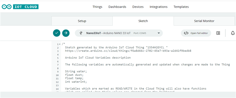
- The sketch is generated on the sketch Tab as described below.
- Here is a screenshot of the sketch generated to send data to the thing that I created on the IoT cloud.
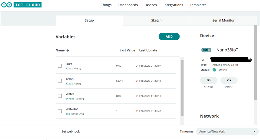
- I then added my code to this sketch to receive serial data, parse the packet to extract the value and set the value to the proper variable
- The variable is then sent to the Thing and onto the Dashboard.
- Here is the entire sketch that will run on the Nano 33 IoT
- Generated Sketch to run on the Nano 33 IoT
- CODE HAS MOVED TO COMMENTS BELOW :
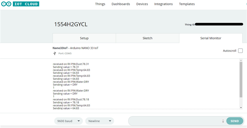
- Here is a screenshot of the Serial Monitor tab on the Arduino CLoud showing the Serial.print() calls in the program running on the Nano 33 IoT.
- And Finally, here is the dashboard showing the Variables.
- On the Phone
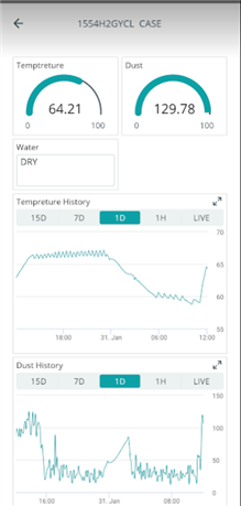
- On the Phone
REFERENCES
Addendum_BLOG_C_References_BLOG5
NEXT
- FOLLOW the following link to the addendum blog that will test running the Test Design Inside the1554H2GYCL Enclosure
-
Addendum BLOG A Testing
- PUTTING THE CASE THROUGH It's Paces.
| <<< PREVIOUS BLOG | NEXT BLOG >>> |
|---|---|
| Blog#6 Conclusion (Case Enclosure Reliability Monitor) |
