

Background
In the first update I have discussed mainly about Würth Elektronik LEDs for this design challenge and their features. I have discussed more about LED parameters, their protocol and how to calculate power requirements for specific LED variant. This data is important and helps us to create right design. For example, knowledge of protocol helps in software development and that of power requirements helps us in creating right PCB design and power supply requirements.
Hence, I kept first blog exclusively for understanding these parameters.
This second blog I am writing for planning for PCB design and how I decided on using different components.
Introduction
This challenge provides a kit with six different kinds of programmable LEDs and some other components such as Taxas Instruments level converters, Arduino board and some other required components to solder these parts and write code.
As I am not that good in soldering and also, I think that the kit requires challengers to work on PCB design and then soldering I decided myself to create a PCB with assembly to avoid complex soldering. Still, I will do some minor soldering as well.
Design Idea
Some time ago, I got a board from Partical that is called SnowFlack. This is a device with 36 RGB LEDs, mic, specker and Wi-Fi/BLE connectivity. This board was interesting idea. Nevertheless, I had same idea in the past and I created some basic PCB and software to change LED color using BLE. But it is not that simple always to create something that one can show to the world.
With this challenge, I decided to create a PCB with Würth Elektronik RGB LEDs. As there are many LEDs recommended for this challenge, I also tried to include these LEDs in my design. Apart from that, I want to run some machine learning code(model) on my device to detect some "keywords" such as for example "RED", "GREEN", "BLUE" to change the color of an LED. I also wanted to try some gesture recognition model to change the color of an LED. For this reason, I have included two microphones and a IMU sensor from TDK Invensense. For LEDs to change color it is required to have microcontroller that can generate PWM waves with different duty cycle requirements. Also, if there is wireless interface, one can use to change the color/effect of LEDs wirelessly. Hence, I have ESP32-S3 based module from Espressif.
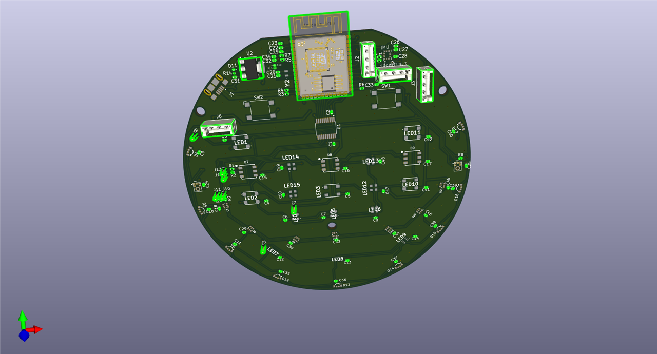
Breakdown of PCB design in KiCad
Power section
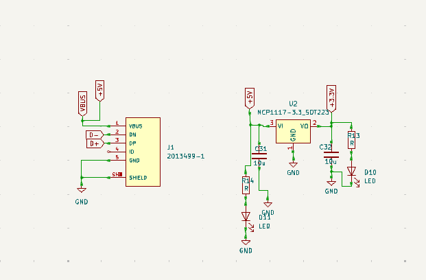
For the PCB design the first required thing is to create a power section with connectors for power or USB. As I am using ESP32-S3 based chip, there is a USB support for this chip already. I am using USB 2.0 connector interface for power and download of code to this chip. As the LEDs are required to be powered with 5V and the chip using 3.3V it is required to have LDO or DC-DC regulators for the power of the design.
The NCP1117-3.3 is the chip used for powering the module. The following diagram shows the schematic diagram for the design with 5V input from the USB and 3.3V output.
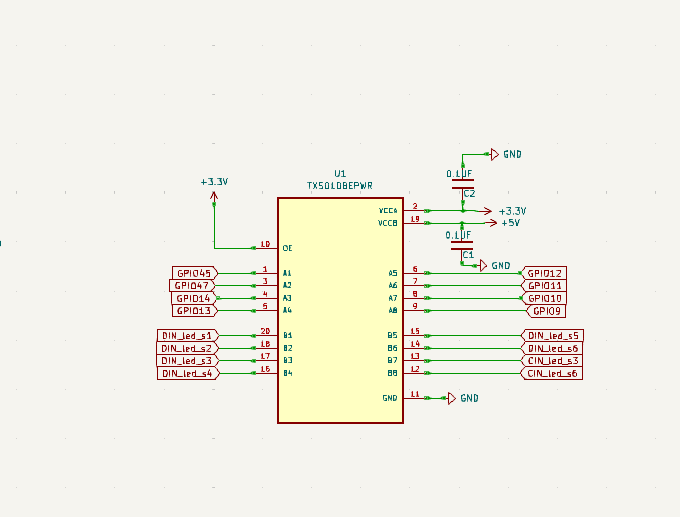
Level converter
As the LEDs are 5V logic level they need to have 5V input PWM wave data from the microcontroller. This level conversion can be achieved using level converter circuit such as from Texas Instruments TXS0108EPWR as show in the following schematic diagram. This will provide the required voltage level conversion for LEDs. It is thus important to understand the datasheet parameters for LEDs. The delay (propagation delay) caused by the level converter should not be more than the permitted. i.e. the delay should not change the meaning of encoded data for the bit values. With TXS0108EPWR it seems very safe for the moment, but I still need to test it during the contest.
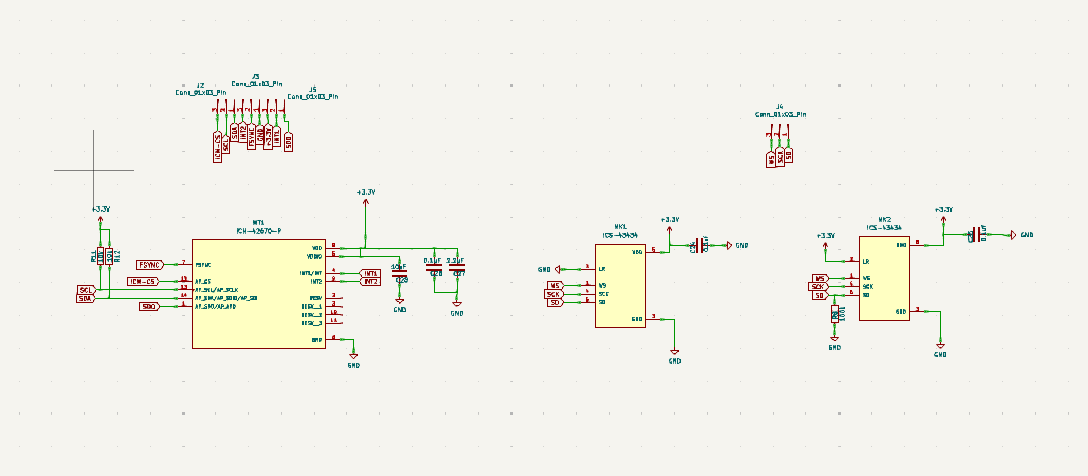
Sensor schematic
The sensors are microphone (ICS-43434) and IMU sensor (ICM-42670-P) both from TDK. Both these sensors have requirements for capacitance tolerance and layout design requirements that must be followed. The datasheet mentions this in detail. For my design, I have followed this guideline carefully.
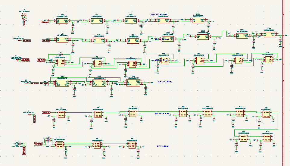
LED schematics
The following is the schematic for RGB LEDs and their connection. I have used all those six LEDs mentioned in the official kit. One challenge was to measure the power requirements of these LEDs and there is a current limit that USB can handle. Also, each GPIO of the chip can handle some amount of current (This won't be an issue as this is a digital signal not handling heavy current, but it is worth notice in case someone is using something like a motor or specker or something that needs high currents).
For this design, I have used following LEDs with MPN from Würth Elektronik.
- Würth Elektronik 1315050930002
- Würth Elektronik 1313210530000
- Würth Elektronik 1312020030000
- Würth Elektronik 1312121320437
- Würth Elektronik 1315050930246
- Würth Elektronik 1311610030140
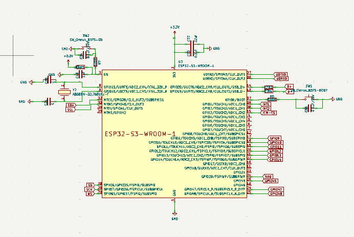
ESP32 - Module Schematic
I am using ESP32-s3 module for this design. This module has onboard Wi-Fi and BLE connection. The module is packed with antenna, flash and other required peripheral circuit for the design.
I have added two buttons for flash download and reset function of the chip. I have also added some capacitors for power supply filtering.
The USB lines (D+ and D-) requires having 90-ohm differential impedance-controlled line. I have calculated these parameters using KiCad calculator during my design.
Conclusion
For the schematic part, I have added enough components to test my design. This design contains chip and other peripherals required for functioning of the board. I have added some more LEDs in my design, and this could be challenging to supply enough current to all those LEDs at once. But I keep this part on testing. One improvement that I might have done is to use USB-3.0 interface to have more current. It can handle up to 1 A of current. But I will find some way to power the board. !

