

Table of Contents
Previously I have wrote two blog posts in this design challenge. This is the Third one.
- First Blog
The first blog was about introduction to the challenge itself and the components. I mentioned in the first blog what are the LEDs that I am going to use from Wurth Elektronik and things such as how to read the datasheet and calculate different parameters such as power, current, etc for the LEDs.
- Second Blog
In the second blog post there was information about the schematic that I have created. I mentioned in detail about each section of my schematic design.
- Third Blog
This is the third blog, and it is going to be more practice. In this post, I will show you the finished PCB (that I received some days ago from NextPCB) and testing of the sections that I designed in Blog-2.
Introduction
After creating the PCB schematic and layout using KiCad, I had ordered the PCB from NextPCB.
The PCB layout was designed in 4-layers as listed in the following order. To make the design interesting, I kept the PCB in a round shape. This will look more beautiful, and layout also will look nicer. In the end when I receive the PCB and start the LEDs, they would look more organized.
For round shape PCB just a good thing to do is to also place components at particular angle.
- TOP COPPER TRACKS
- GND
- POWER
- BOTTOM COPPER TRACKS
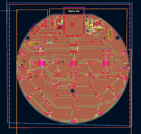
The following layout image from KiCad shows layers and component placements. I have used some planes in the layout to have power stability and GND return path.
For the LEDs as they require 5V, I have a plane that is below LEDs placements. Hence the third layer below all the RGB LEDs is 5V power plane.
There is 3.3V power plane below 3.3V power domain. There is GND plane on entire layer 2 and copper pour on layer 1 and layer 2 for GND signal.
Testing the newly received PCB
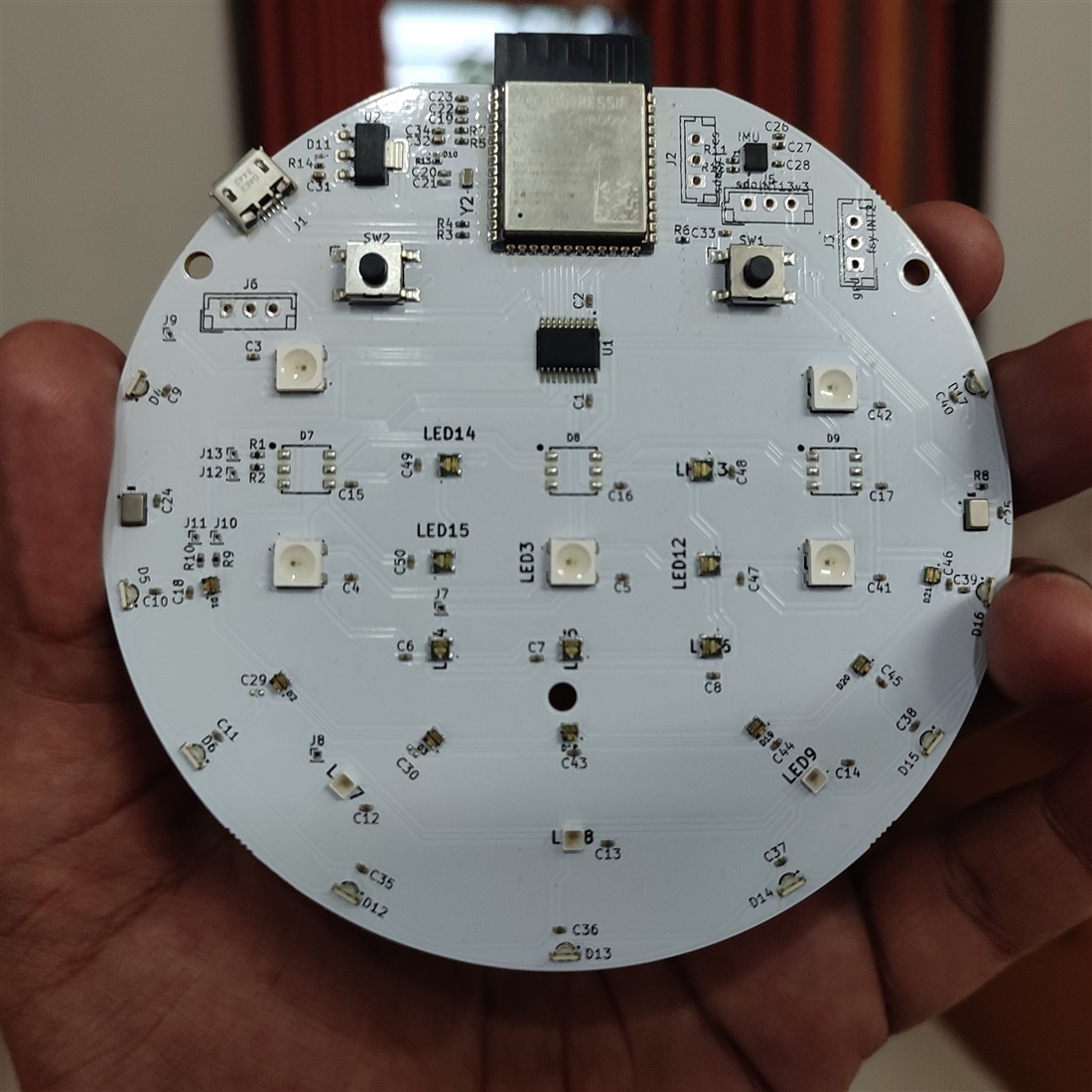
I got this assembled PCB some days ago from NextPCB. The actual device looks similar to the one I had designed and viewed in KiCad 3D viewer. But it is always interesting to see the device in real and have a sense of how it looks. So here it is.
Testing Power Supply
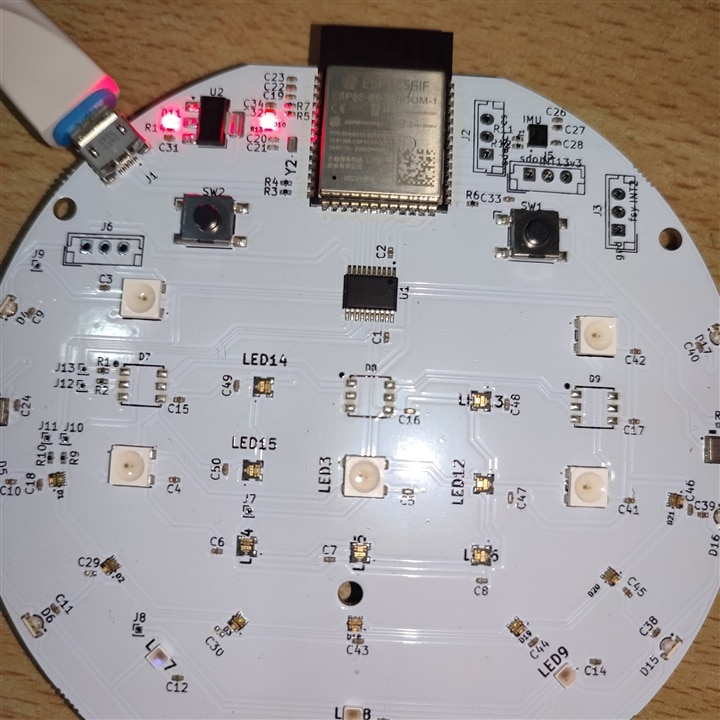
Power supply is important design consideration. As in my design it was required to take out 5v USB signal for LEDs and use 3.3v signal for the ESP32 module. I used NCP-1117-3.3 LDO power regulator for this design. The RED LEDs are the indication that the device is working properly. i.e. Power LEDs.
One thing that I was more concerned about was USB signal and impedance matching to 90 ohms. As my calculation for tracks, width and other paameters to calculate impedance and PCB house's suggestions was different, but I went with their suggestion. And it worked.
As soon as I attached the USB it was detected in windows device manager. Now one can upload the code or run the code if I am not in bootloader mode.
Testing esp32-s3 module
The esp-32 Wroom module contains espressif systems dual-core SoC and it has Wi-Fi/Bluetooth and several peripherals on it. The module comes with external flash chip with 16-MB storage space already there on the package itself. This will help us to collect and store code, run machine learning model, store data, save files and many other advantages.
One of the first thing to test esp-32 chip is to load a simple blink or hello world program. This will let us know if the chip is working or not or it is responding or not. I wanted to give a try to Micro python on the first try but one can start with Arduino or esp-idf.
Installing Micro python
Overview — MicroPython latest documentation
Micropython has a good support for esp32 devices. There are many libraries for wireless communication such as Wi-F-/Bluetooth that are supported for esp32 chips.
Also, there is a good support for peripherals such as SPI, I2C, I2S and others. To run Micro python code on esp32 it is required to first flash the firmware on to the device. The following commands will first erase and then flash the firmware on the device.
python -m esptool --chip esp32 erase_flash
python -m esptool --chip esp32 --port COM7 write_flash -z 0x1000 firmware.bin
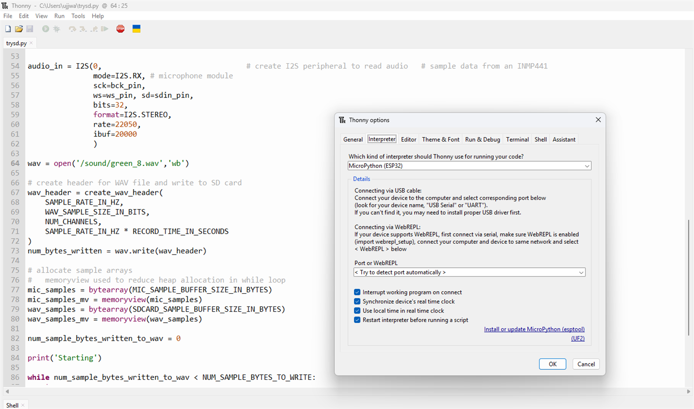
Next one can use IDE such as Thony to run micropython code. This will configure the IDE to run the code on esp32 device. Micropython supports various packages that you can install using the Thony IDE from Tools > Manage Plugin.
Testing of different LEDs
Mainly there are six different kinds if RGB chip LEDs that is there in the kit. All these LEDs are different. But most of them use same protocol that is compatible with neopixel ws2812b kind of LEDs. But there are two LED types that must be operated using two lines namely clock and data. This can be operated using SPI or similar interface where clock and data rate can be matched that of the LED that is supported in the datasheet. From my side I decided to use SPI interface for this. Because it has both clock and data and needs no extra bits such as address or read/write bit in I2C. But I think I2S can also be used, or a GPIO bit-bang technique can also be used. But why to use complex method when we have simple interface ready to be used such as SPI.?
One of the LED uses 16-bits for each color value. Hence it will also need separate code for it's working. Let's discuss each one of them one by one.
1311610030140 LED
The datasheet for this LED has some information about how to get this LED work. Basically, it can work with SPI protocol with some tuning. One thing is that there is a minimum clock duration of approx. 30 nanoseconds. This implies that the frequency of the SPI clock should not be very high. Also, there are four data bytes to be sent in sequence for each LED. Means if I have three LEDs, then I must send 3x4 = 12 bytes of data. Also, there is a start frame of 32x0 bits. Means four bytes. There is end frame of N/2 bits. So, if I have four LEDs connected, I must send some two bits of data. This is very important to notice. If I turn off the SPI clock just after sending data for color, it will not work. I must keep the clock on for at least N/2 bits cycle. The bit values do not matter.
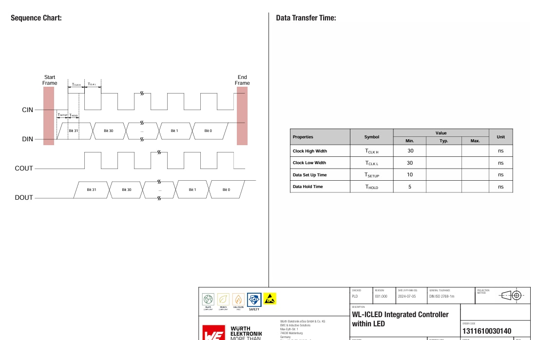
The frame will be like this
- 32 bits x 0 > 4 bytes start frame
- 4 bytes color value
- First byte = [0:2] Flag bits, [3:7] global current gain value
- second byte (Green) + Third byte (Blue) + Fourth byte (Red) values
- End frame of N/2 bits where N = Number of LEDs
Here is the Python code for this LED.
from machine import PWM
import machine
import sys
import time

spi = machine.SPI(2, baudrate=3000000, polarity=0, phase=0, sck=machine.Pin(10), mosi=machine.Pin(14), miso=machine.Pin(38), firstbit=1)

start_frame = bytes([0x00, 0x00, 0x00, 0x00])

color_value0 = bytes([0xBF, 0xFF, 0x00, 0x00])
color_value1 = bytes([0xBF, 0x00, 0xFF, 0x00])
color_value2 = bytes([0xBF, 0x00, 0x00, 0xFF])

end_frame = bytes([0x7])

time.sleep_us(50)
#start frame
spi.write(start_frame)

#data for seven LEDs connected in series
spi.write(color_value0)
spi.write(color_value1)
spi.write(color_value2)

spi.write(color_value0)
spi.write(color_value1)
spi.write(color_value2)

spi.write(color_value0)
spi.write(end_frame)
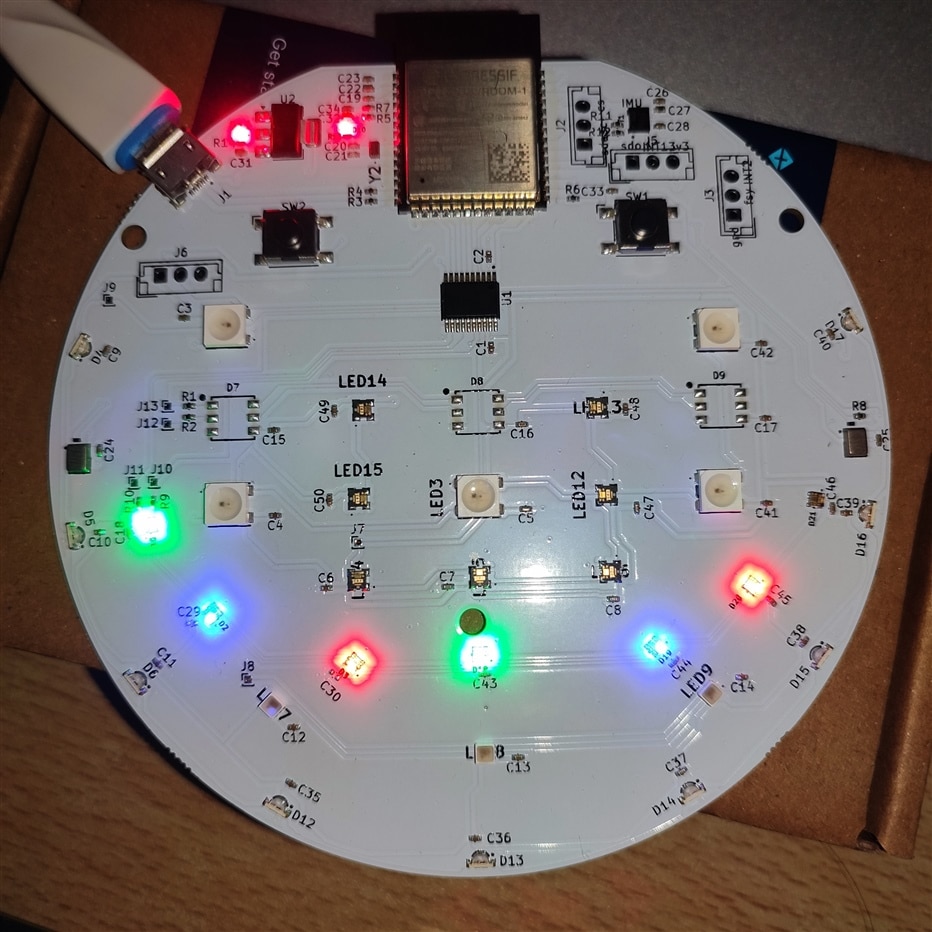
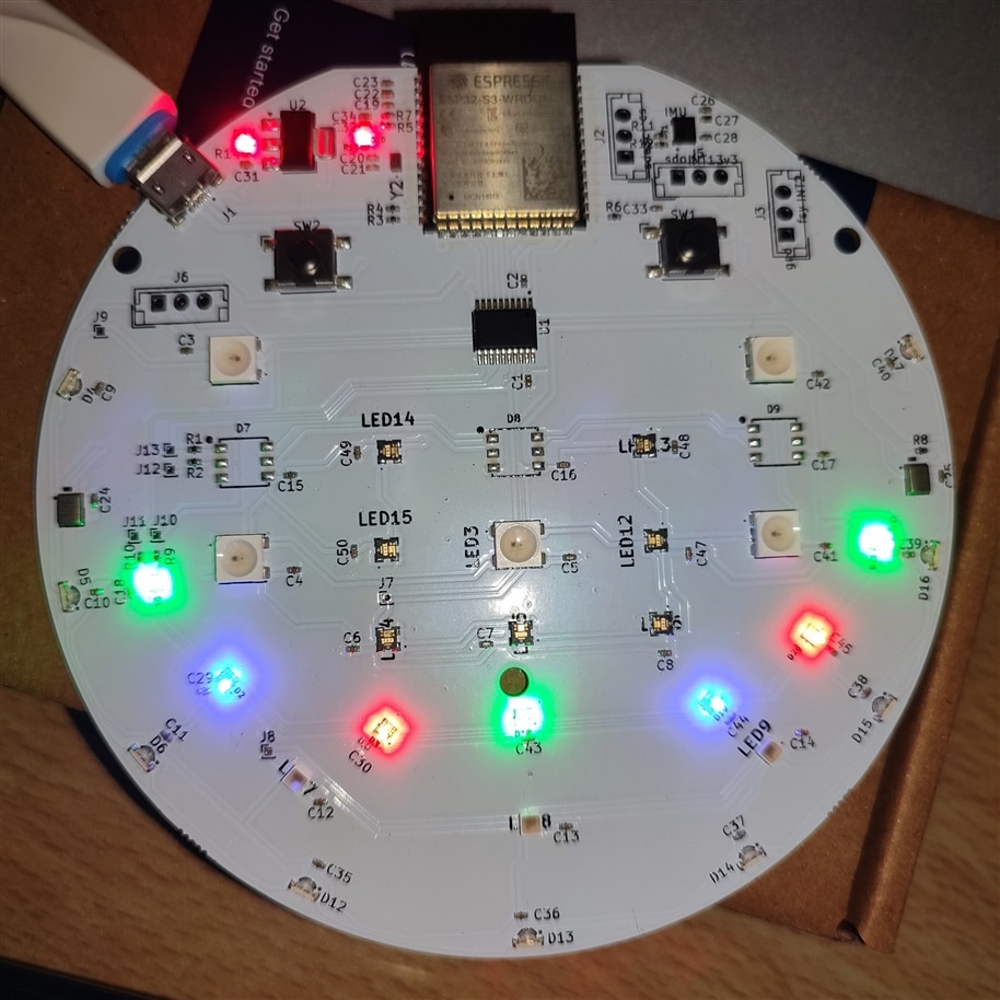
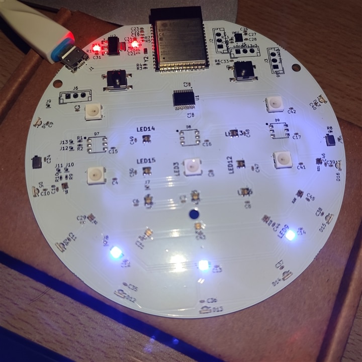
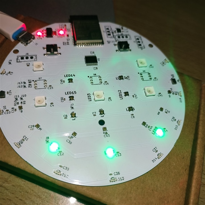
At first, I forget to send the end frame hence the last LED is not ON in the first picture above. Then the last LED is green colored.!
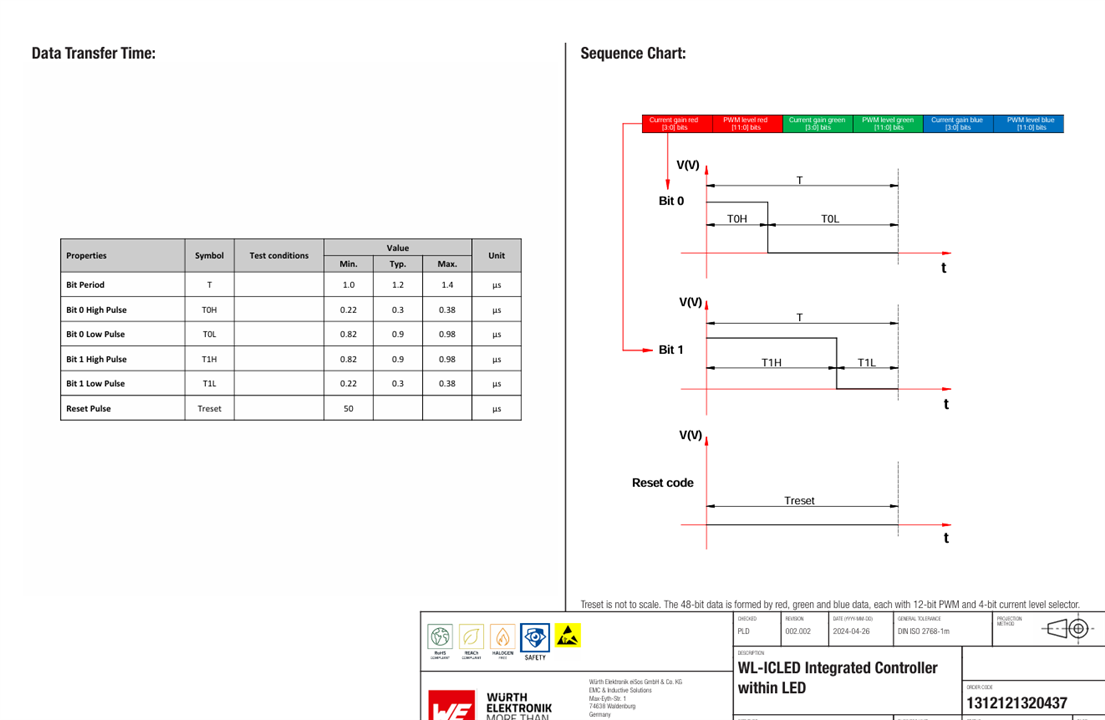
1312121320437 LED
This LED is also different in terms of protocol it works with. Also, this is the LED with Bypass signal. Means if a specific LED is not working then the next LEDs in the series will still work. This can be done by connecting a bypass signal. The LED chip is smart enough to determine that the DOUT of the previous LED has malfunctioned. It will take the input of the previous LED and on BI pin and let the other LEDs connected in series work as expected.
From the datasheet of the LED, it is clear that the LED works similar to ws2812 kind of protocol. But there is some significant difference. First, the data values are 16-bit for each color. The first four bits are for current gain value for each color (0 means no gain and F means highest). Then there is eight-bit color value for each color.
The total time period of a specific bit (0 or 1) is 1.2 us. With high/low time ranging between approx. 0.3 us to 0.9 us. These timing values must be followed to generate signals for the LEDs. At first, I tried to do this with PWM module in micropython but that will not work as PWM is slow in changing duty cycle. Then the option was to use SPI to encode the LED data values and send it over. Also, SPI can be fine-tuned to have accurate pulses.
Here is a simple code to make these LEDs work as expected. I have three LEDs connected in series. I can change the color and current gain using the following code.
from machine import PWM
import machine
import sys
import time

spi = machine.SPI(2, baudrate=8000000, polarity=0, phase=0, sck=machine.Pin(40), mosi=machine.Pin(13), miso=machine.Pin(38), firstbit=0)

def convert_data():
    red = 0x1000
    green = 0x0000
    blue = 0x0000

    color = blue << 32 | green << 16 | red
    data = []

    print(data)
    for j in range(3):
        for i in range(48):
            if((color >> i) & 0x1):
                data.append(0xFC)
            else:
                data.append(0xC0)
    return data

buf = convert_data()
send = bytearray(buf)
spi.write(send)
time.sleep_us(50)
Let the pictures explain it all.
At first the LED is OFF. Then the LEDs turns bit bright. This is because the value for red in the above code is 0x100F. The it turns bit low brighter because the value of red is 0x1001. This is the effect of lowering the current gain. The last is highest current gain and highest bit color intensity value. That is 0xFFFF.
Testing sensors
- IMU
The IMU sensor is Invensense ICM-42670-P. It has features such as motion detection algorithm, Accelerometer and Gyroscope data. It also has inbuilt temperature sensor. The sensor can run on I2C, I3C or SPI interface. As soon as I received this board, I wanted to test whether the sensor can be detected on i2c interface using some simple scan code.
In micropython it is possible to create a simple code that can verify that this sensor is working properly. The following code snippet is able to detect the sensor and read it's ID register value over I2C interface.
_ICM2670P_ADDRESS = 0x68

_TEMP_HIGH = 0x09
_TEMP_LOW = 0x0A
_PWR_MGMT0 = 0x1F


class ICM42670P(object):
    def __init__(self, interface = 1, sda=Pin(39), scl=Pin(40), cs=1, addr_sel=1, _address=_ICM2670P_ADDRESS, freq=400000):
        # ICM42670_P needs CS line HIGH for I2C
        # interface and needs addr_sel pin to be
        # HIGH/LOW for address selection

        cs = Pin(3, Pin.OUT)
        addr_sel = Pin(38, Pin.OUT)

        cs.value(1)
        addr_sel.value(0)

        self.i2c = I2C(1, sda=Pin(39), scl=Pin(40))

        print(self.i2c.scan())
        who_am_i = 0
        who_am_i = self.i2c.readfrom_mem(_ICM2670P_ADDRESS, 0x75, 1)
        data = int.from_bytes(who_am_i)
        print(hex(data))
- Microphone
The microphone is from Invensense that is ICS-43434 which is connected over I2S interface. For me, I2S was new but there is a module in micropython to make things easier. I2S uses three pins for capturing audio data. Namely,
- SCK > Clock signal
- WS > Left/Right word select (mono/Sterio selection)
- SD > Serial Data.
The main question to my mind was how to test these microphones and verify that it is working as expected?
As I do not have memory card slot or any other means such as specker to store the recorded voice or play it, I must use internal flash memory to store the data and then send it over some interface. Or I can use USB audio class or similar to send these data over USB. Some other suggestions might be to use Wi-Fi to send these files over TCP/UDP. None of these suggestions are simple. But I can use the internal flash and then following command to send the recorded audio file to host PC for analysis.
mpremote cp -r :/sound C:\Users\Downloads
The following is a simple code to run I2S peripheral and store the .wav file into the internal flash of the esp32 device. The code generates wav header and stores raw I2S data into a format that than can be transferred to the host PC.
from machine import ADC, I2C, Pin, I2S, freq, SPI, SDCard
import time
import os
from time import sleep
import neopixel, machine
import uos

#======= USER CONFIGURATION =======
RECORD_TIME_IN_SECONDS = 30
SAMPLE_RATE_IN_HZ = 22050

#======= USER CONFIGURATION =======
WAV_SAMPLE_SIZE_IN_BITS = 16
WAV_SAMPLE_SIZE_IN_BYTES = WAV_SAMPLE_SIZE_IN_BITS // 8
MIC_SAMPLE_BUFFER_SIZE_IN_BYTES = 4096
SDCARD_SAMPLE_BUFFER_SIZE_IN_BYTES = MIC_SAMPLE_BUFFER_SIZE_IN_BYTES // 2

NUM_SAMPLE_BYTES_TO_WRITE = RECORD_TIME_IN_SECONDS * SAMPLE_RATE_IN_HZ * WAV_SAMPLE_SIZE_IN_BYTES
NUM_SAMPLES_IN_DMA_BUFFER = 256
NUM_CHANNELS = 2


#sd = machine.SDCard(slot=2, cs=machine.Pin(40))

def snip_16_mono(samples_in, samples_out):
    num_samples = len(samples_in) // 4
    for i in range(num_samples):
        samples_out[2*i] = samples_in[4*i + 2]
        samples_out[2*i + 1] = samples_in[4*i + 3]

    return num_samples * 2

def create_wav_header(sampleRate, bitsPerSample, num_channels, num_samples):
    datasize = num_samples * num_channels * bitsPerSample // 8
    o = bytes("RIFF",'ascii')                                                   # (4byte) Marks file as RIFF
    o += (datasize + 36).to_bytes(4,'little')                                   # (4byte) File size in bytes excluding this and RIFF marker
    o += bytes("WAVE",'ascii')                                                  # (4byte) File type
    o += bytes("fmt ",'ascii')                                                  # (4byte) Format Chunk Marker
    o += (16).to_bytes(4,'little')                                              # (4byte) Length of above format data
    o += (1).to_bytes(2,'little')                                               # (2byte) Format type (1 - PCM)
    o += (num_channels).to_bytes(2,'little')                                    # (2byte)
    o += (sampleRate).to_bytes(4,'little')                                      # (4byte)
    o += (sampleRate * num_channels * bitsPerSample // 8).to_bytes(4,'little')  # (4byte)
    o += (num_channels * bitsPerSample // 8).to_bytes(2,'little')               # (2byte)
    o += (bitsPerSample).to_bytes(2,'little')                                   # (2byte)
    o += bytes("data",'ascii')                                                  # (4byte) Data Chunk Marker
    o += (datasize).to_bytes(4,'little')                                        # (4byte) Data size in bytes
    return o

bck_pin = Pin(36)
ws_pin = Pin(37)
sdin_pin = Pin(35)

audio_in = I2S(0,                                 # create I2S peripheral to read audio   # sample data from an INMP441
               mode=I2S.RX, # microphone module
               sck=bck_pin,
               ws=ws_pin, sd=sdin_pin,
               bits=32,
               format=I2S.STEREO,
               rate=22050,
               ibuf=20000
               )

wav = open('/sound/green_8.wav','wb')

# create header for WAV file and write to SD card
wav_header = create_wav_header(
    SAMPLE_RATE_IN_HZ,
    WAV_SAMPLE_SIZE_IN_BITS,
    NUM_CHANNELS,
    SAMPLE_RATE_IN_HZ * RECORD_TIME_IN_SECONDS
)
num_bytes_written = wav.write(wav_header)

# allocate sample arrays
#   memoryview used to reduce heap allocation in while loop
mic_samples = bytearray(MIC_SAMPLE_BUFFER_SIZE_IN_BYTES)
mic_samples_mv = memoryview(mic_samples)
wav_samples = bytearray(SDCARD_SAMPLE_BUFFER_SIZE_IN_BYTES)
wav_samples_mv = memoryview(wav_samples)

num_sample_bytes_written_to_wav = 0

print('Starting')

while num_sample_bytes_written_to_wav < NUM_SAMPLE_BYTES_TO_WRITE:
    try:
        # try to read a block of samples from the I2S microphone
        # readinto() method returns 0 if no DMA buffer is full
        num_bytes_read_from_mic = audio_in.readinto(mic_samples_mv)
        if num_bytes_read_from_mic > 0:
            # snip upper 16-bits from each 32-bit microphone sample
            num_bytes_snipped = snip_16_mono(mic_samples_mv[:num_bytes_read_from_mic], wav_samples_mv)
            num_bytes_to_write = min(num_bytes_snipped, NUM_SAMPLE_BYTES_TO_WRITE - num_sample_bytes_written_to_wav)
            # write samples to WAV file
            num_bytes_written = wav.write(wav_samples_mv[:num_bytes_to_write])
            num_sample_bytes_written_to_wav += num_bytes_written
    except (KeyboardInterrupt, Exception) as e:
        print('caught exception {} {}'.format(type(e).__name__, e))
        break
Next steps
I am completing this blog here as there is still things to be done. I have not explained all the LEDs in this blog, and I will explain about them in the upcoming blog posts. This is because it could be so much in one blog. So please wait for the next blog posts. Also, at the moment it is not possible to save the work in blog and post latter. I think this should be changed so that one can post blogs latter after editing their posts.! JoBatcliffe (joratcliffe)
My idea for this challenge and next blogs is also to create a keyword detection model and using some ML platforms such as Edge Impulse or similar to train the model and change the LED colors accordingly.
There is also IMU sensor in this device and that can also run some gesture detection models. Let me see.! Stay tuned.

