

Table of Contents
Introduction
In the previous blog post, I have talked about different LED types from Wurth Electronics kit in this challenge. This blog post will be more about the progress that I have made so far and remaining parts of the previous blog post.
Testing of different LEDs
In the blog-3 of this challenge, I have discussed about some LEDs, and the others were yet to be discussed. In this blog post I am discussing about those LEDs.
As I am using MicroPython for development and software it is important to note that all the LEDs are not compatible with neopixel library provided by Micropython. Well, that is not a burden to me at all. But it is important to note.
The LEDs discussed in this blog post are all compatible with Neopixel format. This is because some LEDs do have different timing and protocol requirements. Such that for those LEDs sometimes separate clock signal is required.
Along with clock signal it needs data line. So for these LEDs it is required to have a detailed look on their datasheet and develop driver to drive those LEDs.
Most common workaround would be to use interface such as SPI, I2S, etc. These protocols can generate the data required by the different LED types.
In the previous blog post, I have used hardware SPI interface to send data to this LEDs. It took me some time to understand the exact bit format for this LEDs. But right frequency on SCK and properly encoded data could make it possible for anyone to work with these LEDs.
1313210530000 LED
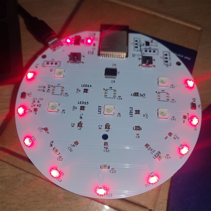
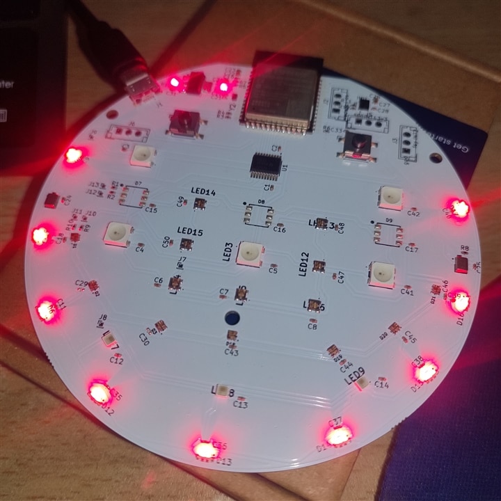
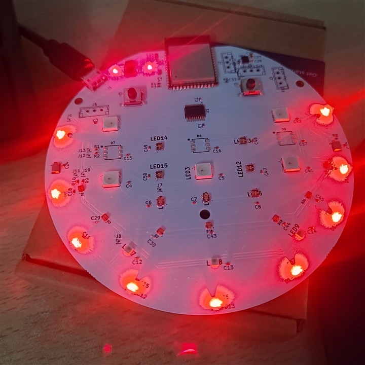
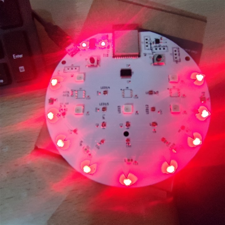
From all the LEDs in the kit this one is the smallest one. When I started creating PCB, I thought that it would be nice to place these LEDs on the rounded corner of the PCB. This LEDs are suitable for tiny size requirements or to create some designs on the PCB like letters or logo etc. due to its small size. It is compatible with Neopixel library.
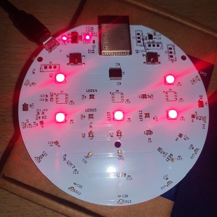
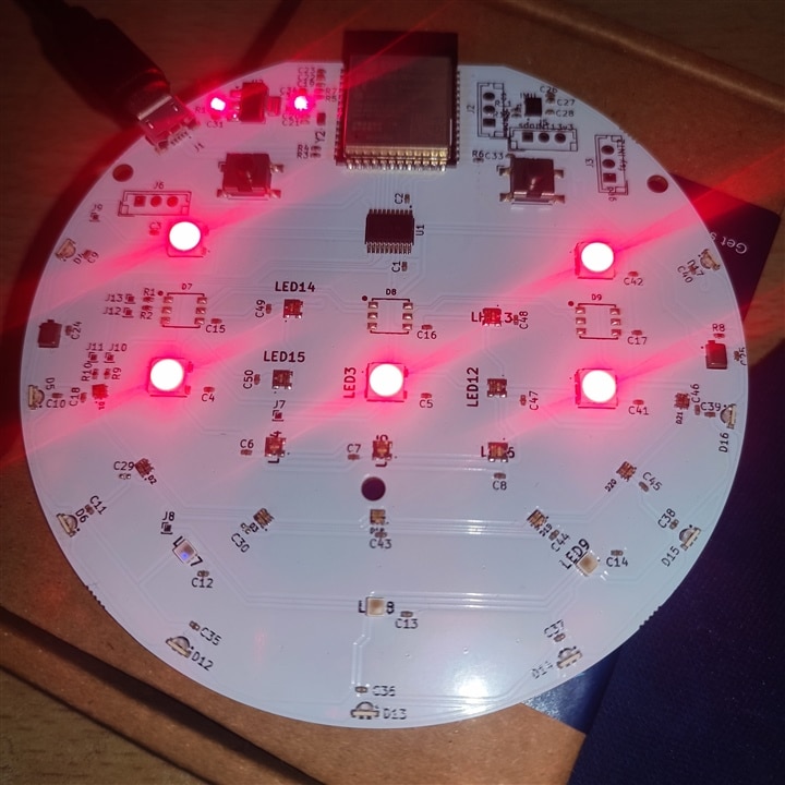
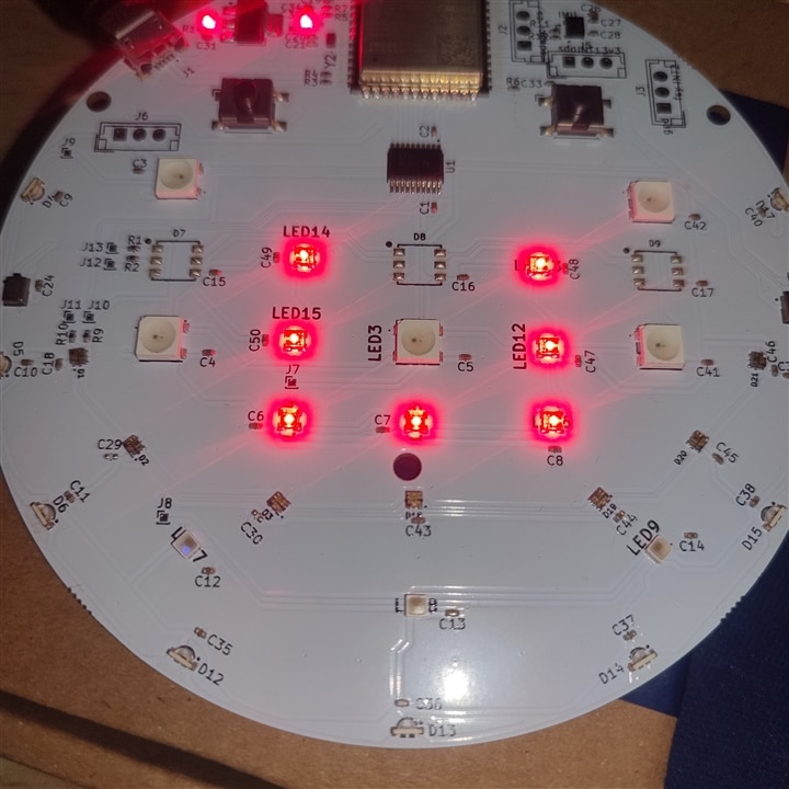
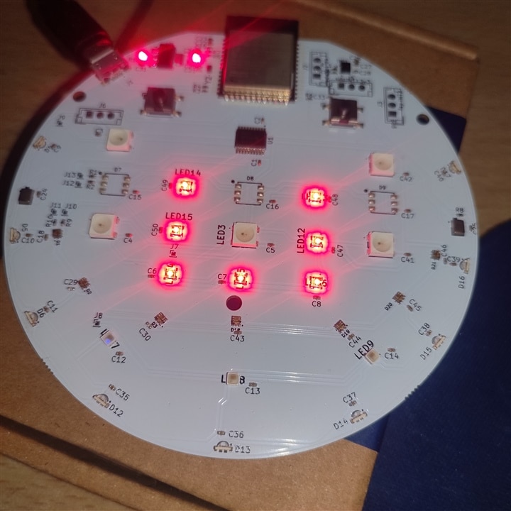
| {gallery}LEDs |
|---|
|
|
|
|
|
|
|
|
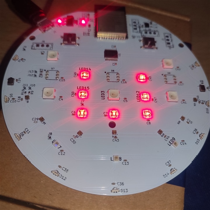
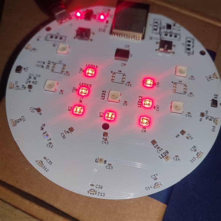
1315050930002 LED
These LEDs are somewhat big in size and has 4 pins. In my opinion this is exact replacement of ws-2812b type of LEDs. It is suitable for lighting application in home, office or anything similar. It can change colors so can be used for applications that require color
1312020030000 LED
These are tiny LEDs that can run with Neopixel format. These are also tiny LEDs with nice color spread. It can be used for decorative lights, home applications and other similar applications.
import time
import machine, network
import espnow
import ubinascii
import neopixel

ledcorner = machine.Pin(12)
ledfive = machine.Pin(45)
ledseven = machine.Pin(47)

neopixelcorner = neopixel.NeoPixel(ledcorner, 9)
neopixelfive = neopixel.NeoPixel(ledfive, 5)
neopixelseven = neopixel.NeoPixel(ledseven, 7)

red = 0
green = 255
blue = 0

while(1):
    for i in range(9):
        neopixelcorner[i] = (red, green, blue)

    for i in range(5):
        neopixelfive[i] = (red, green, blue)

    for i in range(7):
        neopixelseven[i] = (red, green, blue)

    #neopixelcorner.write()
    #neopixelfive.write()
    neopixelseven.write()
Controlling LED color using Wi-Fi
ESPNOW is a Wi-Fi based protocol for wireless communication. It offers simple point-to-point connection between devices.
With ESPNOW it is possible to connect upto 20 devices simultaneously. The protocol does not require complex setup and AP/STA mode requirements.
Another advantage is that ESPNOW can operate for quite long range than traditional Wi-Fi or Bluetooth communication. It can range up to 1.2 kms. This makes it quite suitable for smart light and remote control-based application.
For now, I have tried a simple remote control to change LED color to either RED, GREEN or BLUE based on the status of the push button press on the sending device.
Use of remote control to change LED light color and intensity is more common than using something else. Like for example WiFi or Bluetooth. It eliminates complex setup and cost related to software development and it's faster than other methods. Also, security is not an issue with remote control.
In the Python code for control of the colors of LEDs one just need the MAC address of the sender and the receiver node for point-to-point communication.
Here is the code for sender node. The sender node checks for push button press and if a specific button is pressed then the color on the other side will change to specific color. There are only three pushbuttons so only three colors are possible.
#This is a sender for changing LED colors based on button values

import time
import machine
import espnow
import network
from machine import ADC
import ubinascii

sender = network.WLAN(network.WLAN.IF_STA)
sender.active(True)

mac_bytes = sender.config('mac')
mac_address = ubinascii.hexlify(mac_bytes, ':').decode().upper()
print(mac_address)

espnow = espnow.ESPNow()
espnow.active(True)

receiver = b'\x10\x20\xBA\x59\x7A\xC8'

espnow.add_peer(receiver)

sw2 = ADC(machine.Pin(1))
sw3 = ADC(machine.Pin(2))
sw4 = ADC(machine.Pin(3))

time.sleep(2)

while(1):
    red = sw2.read()
    print(red)

    green = sw3.read()
    print(green)

    blue = sw4.read()
    print(blue)
    send = bytearray(3)

    if red == 0:
        send[0] = 0
        send[1] = 255
        send[2] = 255
        espnow.send(receiver, send, True)
        time.sleep(1)

    if blue == 0:
        send[0] = 255
        send[1] = 0
        send[2] = 255
        espnow.send(receiver, send, True)
        time.sleep(1)

    if green == 0:
        send[0] = 255
        send[1] = 255
        send[2] = 0
        espnow.send(receiver, send, True)
        time.sleep(1)

    time.sleep(1)
Here is the code for the receiver node. In this case the RGB-Matrix PCB. The code continuously checks for new values on ESPNOW network and changes the color of the LED if there is a new value.
# 7C:DF:A1:07:BE:A6
# Receiving the espnow packate and changing the LED colors to RED | GREEN | BLUE
# depending on the button pressed

import time
import machine, network
import espnow
import ubinascii
import neopixel

receiver = network.WLAN(network.WLAN.IF_STA)
receiver.active(True)

mac_bytes = receiver.config('mac')
mac_address = ubinascii.hexlify(mac_bytes, ':').decode().upper()
print(mac_address)

espnow = espnow.ESPNow()
espnow.active(True)

sender = b'\x7C\xDF\xA1\x07\xBE\xA6'
espnow.add_peer(sender)

ledcorner = machine.Pin(12)
ledfive = machine.Pin(45)
ledseven = machine.Pin(47)

neopixelcorner = neopixel.NeoPixel(ledcorner, 9)
neopixelfive = neopixel.NeoPixel(ledfive, 5)
neopixelseven = neopixel.NeoPixel(ledseven, 7)

red = 255
green = 0
blue = 0

while(1):
    for i in range(9):
        neopixelcorner[i] = (red, green, blue)

    for i in range(5):
        neopixelfive[i] = (red, green, blue)

    for i in range(7):
        neopixelseven[i] = (red, green, blue)

    neopixelcorner.write()
    neopixelfive.write()
    neopixelseven.write()

    mac, msg = espnow.recv()
#     print(mac)
#     print(msg[0])
#     print(msg[1])
#     print(msg[2])

    if(msg[0] == 0):
        red = 255
        green = 0
        blue = 0

    if(msg[1] == 0):
        red = 0
        green = 255
        blue = 0

    if(msg[2] == 0):
        red = 0
        green = 0
        blue = 255

    time.sleep(1)
Final thoughts
For this blog, I have keep it simple. But I have also trained ML model on Edge-Impulse and want to try that on this device. The model can detect keywords to change LED colors. Another possibility would be to use libraries such as Emlearn to train and develop ML model. But this can be challenging on tiny devices such as SoC or microcontrollers. Such tiny devices have less memory and have less RAM to fit the model accurately. Emlearn has an advantage that it is compatible with Micropython devices.
