element14 Community
element14 Community
    Register Log In
  • Site
  • Search
  • Log In Register
  • Community Hub
    Community Hub
    • What's New on element14
    • Feedback and Support
    • Benefits of Membership
    • Personal Blogs
    • Members Area
    • Achievement Levels
  • Learn
    Learn
    • Ask an Expert
    • eBooks
    • element14 presents
    • Learning Center
    • Tech Spotlight
    • STEM Academy
    • Webinars, Training and Events
    • Learning Groups
  • Technologies
    Technologies
    • 3D Printing
    • FPGA
    • Industrial Automation
    • Internet of Things
    • Power & Energy
    • Sensors
    • Technology Groups
  • Challenges & Projects
    Challenges & Projects
    • Design Challenges
    • element14 presents Projects
    • Project14
    • Arduino Projects
    • Raspberry Pi Projects
    • Project Groups
  • Products
    Products
    • Arduino
    • Avnet Boards Community
    • Dev Tools
    • Manufacturers
    • Multicomp Pro
    • Product Groups
    • Raspberry Pi
    • RoadTests & Reviews
  • About Us
  • Store
    Store
    • Visit Your Store
    • Choose another store...
      • Europe
      •  Austria (German)
      •  Belgium (Dutch, French)
      •  Bulgaria (Bulgarian)
      •  Czech Republic (Czech)
      •  Denmark (Danish)
      •  Estonia (Estonian)
      •  Finland (Finnish)
      •  France (French)
      •  Germany (German)
      •  Hungary (Hungarian)
      •  Ireland
      •  Israel
      •  Italy (Italian)
      •  Latvia (Latvian)
      •  
      •  Lithuania (Lithuanian)
      •  Netherlands (Dutch)
      •  Norway (Norwegian)
      •  Poland (Polish)
      •  Portugal (Portuguese)
      •  Romania (Romanian)
      •  Russia (Russian)
      •  Slovakia (Slovak)
      •  Slovenia (Slovenian)
      •  Spain (Spanish)
      •  Sweden (Swedish)
      •  Switzerland(German, French)
      •  Turkey (Turkish)
      •  United Kingdom
      • Asia Pacific
      •  Australia
      •  China
      •  Hong Kong
      •  India
      •  Korea (Korean)
      •  Malaysia
      •  New Zealand
      •  Philippines
      •  Singapore
      •  Taiwan
      •  Thailand (Thai)
      • Americas
      •  Brazil (Portuguese)
      •  Canada
      •  Mexico (Spanish)
      •  United States
      Can't find the country/region you're looking for? Visit our export site or find a local distributor.
  • Translate
  • Profile
  • Settings
Light Up Your Life
  • Challenges & Projects
  • Design Challenges
  • Light Up Your Life
  • More
  • Cancel
Light Up Your Life
Forum Smart car chamber #3 Comparisons of WL-ICLED Integrated Controllers and schematic designs
  • News
  • Forum
  • Projects
  • DC
  • Leaderboard
  • Files
  • Members
  • More
  • Cancel
  • New
Join Light Up Your Life to participate - click to join for free!
Actions
  • Share
  • More
  • Cancel
Forum Thread Details
  • Replies 0 replies
  • Subscribers 46 subscribers
  • Views 13 views
  • Users 0 members are here
  • Light Up Your Life
Related

Smart car chamber #3 Comparisons of WL-ICLED Integrated Controllers and schematic designs

fyaocn
fyaocn 1 day ago
The WL-ICLED series, developed by Würth Elektronik eiSos GmbH & Co. KG, consists of integrated RGB LED controllers designed for general electronic equipment .
All models share core features—AlInGaP + InGaN chip technology for red (R)、green (G)、blue (B) emission, RoHS/REACh compliance, halogen-free construction, and low photobiological risk —but differ significantly in packaging, electrical performance, wiring design, and application suitability.
With detailed breakdown and comparison, especially on wiring and key distinctions, to show all the six schematic design and PCB design.

1. Overview of Individual Models

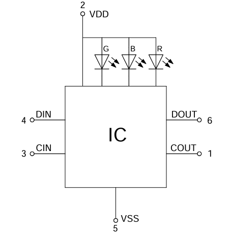
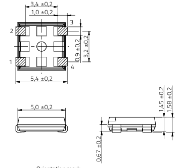
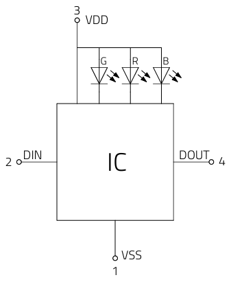
1.1 Model 1311610030140: Chip IC RGB LED Compact

This is a compact chip-level RGB LED controller with a 6-pin configuration (COUT, VDD, CIN, DOUT, VSS, DIN) and a waterclear plastic housing. Its key specifications include:
  • Electrical Limits: 5.5V supply voltage, 100mW power dissipation, 17.5mA total IC current, and 4000V ESD tolerance (Human Body Model, HBM).
  • Optical Performance: Peak wavelengths of 630nm (R)、520nm (G)、465nm (B); luminous intensity ranges 40-80mcd (R)、60-120mcd (G)、15-50mcd (B); and a 120° viewing angle.
  • Wiring Design: Utilizes a synchronous clock-data (CIN/COUT) + serial data (DIN/DOUT) architecture. CIN (Clock In) and COUT (Clock Out) handle clock signal transmission, while DIN (Data In) and DOUT (Data Out) manage serial data, enabling cascading of multiple LEDs. The 32-bit frame data includes 3 flag bits, 5 global current gain bits, and 8-bit PWM levels for each color (G→B→R order), with a 20kHz PWM frequency. A 1ms wake-up time is required after exiting sleep mode.
  • Application: Ideal for compact, low-power scenarios (e.g., small indicator lights) due to its miniaturized chip form and moderate current output.

The size of 16x16 mm with 
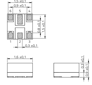
image

and the schematic

image

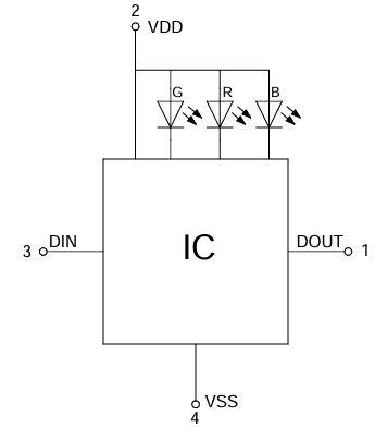
1.2 Model 1312020030000: Chip LED Compact IC RGB

A 4-pin compact chip controller (VDD, DIN, DOUT, VSS) with a waterclear lens, optimized for simplified serial communication. Key traits:
  • Electrical Limits: 5.5V supply voltage, 110mW power dissipation, 6.5mA max IC output current, and 4000V ESD tolerance.
  • Optical Performance: Identical peak wavelengths to 1311610030140, but with a lower PWM frequency (4-6kHz) and matching luminous intensity ranges.
  • Wiring Design: Eliminates dedicated clock pins (CIN/COUT) and adopts a 2-wire serial interface (DIN/DOUT). Data is encoded via pulse width modulation (PWM): Bit 0 uses a 0.15-0.45μs high pulse (T0H) and 0.75-1.05μs low pulse (T0L), while Bit 1 uses a 0.75-1.05μs high pulse (T1H) and 0.15-0.45μs low pulse (T1L). A >200μs reset pulse initializes communication. The 24-bit data frame is ordered G→R→B (8 bits each), with MSB (Most Significant Bit) first transmission.
  • Application: Suited for cost-sensitive, space-constrained designs (e.g., consumer electronics indicators) where simplified wiring reduces PCB complexity.

The size of 20x20 mm
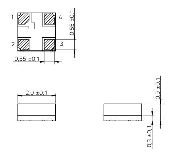
image

schematic

image

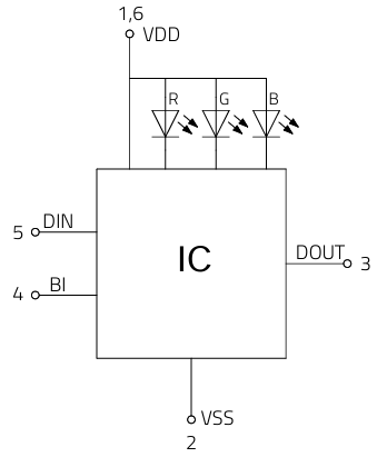
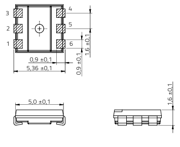
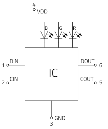
1.3 Model 1312121320437: SMT PLCC6 IC RGB LED

A surface-mount (SMT) PLCC6 (Plastic Leaded Chip Carrier 6-pin) controller with a diffused white housing, designed for high-brightness, industrial-grade applications. Key specifications:
  • Electrical Limits: 5.5V supply voltage, 380mW power dissipation (3.8x that of 1311610030140), 23mA max IC output current, and 2000V ESD tolerance (lower than other models). It also includes a BI (Bypass) pin for emergency shutdown.
  • Optical Performance: Significantly higher luminous intensity (400-600mcd R、700-1000mcd G、160-240mcd B) and narrower spectral bandwidths (14nm R、28nm G、18nm B) for more precise color control; 110° viewing angle.
  • Wiring Design: Features a 6-pin configuration (VDD1, VSS, DOUT, BI, DIN, VDD6) with dual VDD pins (1 and 6) for stable power delivery in high-current scenarios. The BI pin allows direct bypassing of the controller to turn off LEDs instantly. Data transmission uses 48-bit frames (12-bit PWM + 4-bit current gain per color, R→G→B order) and a low PWM frequency (0.5-0.7kHz) to prioritize brightness stability over flicker reduction. A 50μs reset pulse is required, shorter than most models.
  • Application: Industrial lighting, large display panels, or outdoor indicators, where high brightness and robust power handling are critical.

the size of 22x 22 mm
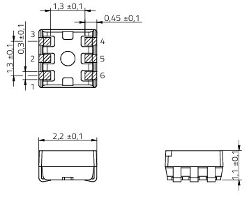
image

schematic,

Pin 1 and Pin 6 both are VDD for easy power access

image

1.4 Model 1313210530000: Side View IC RGB LED

A 4-pin side-emitting controller (DIN, VDD, VSS, DOUT) with a waterclear lens, designed for edge-lighting scenarios. Key traits:
  • Electrical Limits: 5.5V supply voltage, 110mW power dissipation, 6.5mA max IC output current, and 4000V ESD tolerance—matching 1312020030000.
  • Optical Performance: Identical peak wavelengths and luminous intensity to 1312020030000, but with a side-emitting optical design (120° viewing angle) for edge illumination.
  • Wiring Design: Shares the 2-wire serial interface (DIN/DOUT) of 1312020030000, with identical bit timing (T0H、T0L、T1H、T1L) and 24-bit G→R→B data frames. The only physical difference is the side-mounted pin layout, which requires PCB traces optimized for edge placement.
  • Application: Edge-lit displays (e.g., LCD backlights, automotive dashboard indicators) where light emission from the side is required.

the size of 32x16 mm

image

schematic

image

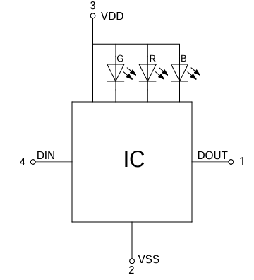
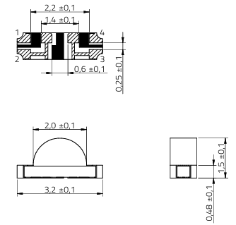
1.5 Model 1315050930002: SMT PLCC4 IC RGB LED

A 4-pin SMT PLCC4 controller (VSS, DIN, VDD, DOUT) with a diffused white housing, balancing brightness and compactness. Key specifications:
  • Electrical Limits: 5.5V supply voltage, 240mW power dissipation, 14.5mA max IC output current, and 4000V ESD tolerance.
  • Optical Performance: High luminous intensity (280-450mcd R、900-1300mcd G、150-260mcd B) and 120° viewing angle, with spectral bandwidths matching 1312121320437.
  • Wiring Design: Uses a 4-pin serial interface (DIN/DOUT + VDD/VSS) with unique bit timing: Bit 0 (T0H=320-400μs, T0L=800-900μs) and Bit 1 (T1H=640-800μs, T1L=350-400μs)—slower than 1312020030000 to improve data stability. The 24-bit G→R→B data frame and >200μs reset pulse are consistent with 4-pin chip models, but the PLCC4 package allows for easier SMT assembly than chip-level designs.
  • Application: Mid-brightness applications (e.g., home automation panels, retail signage) where SMT compatibility and moderate brightness are needed.

the size of 50x50 mm

image

schematic

image

1.6 Model 1315050930246: SMT PLCC6 IC RGB LED

A high-performance 6-pin SMT PLCC6 controller (DIN, CIN, VSS, VDD, COUT, DOUT) with a diffused white housing, designed for high-current, high-brightness cascading. Key traits:
  • Electrical Limits: 5.5V supply voltage, 360mW power dissipation, 65mA total IC current (highest in the series), 21mA typical IC output current, and 4000V ESD tolerance.
  • Optical Performance: Highest luminous intensity in the series (560-800mcd R、900-1800mcd G、285-400mcd B) and 120° viewing angle, with 20kHz PWM frequency for flicker-free operation.
  • Wiring Design: Revives the clock-data (CIN/COUT) + serial data (DIN/DOUT) architecture of 1311610030140 but optimizes it for high-current cascading. CIN/COUT handle synchronous clock signals (30ns min clock high/low width), while DIN/DOUT manage serial data (10ns setup time, 5ns hold time). The 32-bit frame data includes 3 flag bits (with sleep mode enable via 3’b101), 5 global current gain bits, and 8-bit PWM levels (B→G→R order). A 1ms wake-up time and 20kHz PWM frequency make it suitable for high-density LED arrays.
  • Application: Large-scale lighting systems (e.g., architectural lighting, stage lights) where cascading multiple high-brightness LEDs is required.

the size of 50x50 mm

image

schematic

image

2. Key Comparisons: Wiring and Core Differences

2.1 Wiring Architecture: 2-Wire vs. 4-Wire

The most impactful distinction across models is their wiring design, which dictates compatibility with cascading, PCB complexity, and data stability:
Wiring Type Models Pins Involved Data/Clock Handling Cascading Capability Best For
2-Wire Serial 1312020030000, 1313210530000, 1315050930002 DIN, DOUT Data encoded via pulse width (no dedicated clock pin) Limited (relies on precise pulse timing) Compact, low-density designs
4-Wire (Clock + Data) 1311610030140, 1315050930246 DIN, DOUT, CIN, COUT Separate clock (CIN/COUT) and data (DIN/DOUT) signals Excellent (synchronous clock reduces timing errors) High-density cascading (e.g., LED arrays)
  • 2-Wire Advantages: Fewer PCB traces, lower cost, and simpler assembly.
  • 4-Wire Advantages: More stable data transmission, support for longer cascading chains, and higher PWM frequencies (20kHz vs. 4-6kHz).

2.2 Electrical and Optical Differences

Parameter 1311610030140 1312020030000 1312121320437 1313210530000 1315050930002 1315050930246
Power Dissipation 100mW 110mW 380mW 110mW 240mW 360mW
Max IC Current 17.5mA 6.5mA 23mA 6.5mA 14.5mA 65mA
ESD Tolerance (HBM) 4000V 4000V 2000V 4000V 4000V 4000V
PWM Frequency 20kHz 4-6kHz 0.5-0.7kHz 4-6kHz 2.5kHz 20kHz
Luminous Intensity (Typ.) 80/120/50mcd 80/120/50mcd 600/1000/240mcd 80/120/50mcd 450/1300/260mcd 800/1800/400mcd
  • High-Power Models: 1312121320437 (380mW) and 1315050930246 (360mW) handle higher currents for bright, industrial applications.
  • Low-Power Models: 1312020030000 and 1313210530000 (110mW) suit consumer electronics with minimal power budgets.

2.3 Packaging and Mechanical Differences

Package Type Models Housing/Lens Pin Count Mounting Use Case
Chip Compact 1311610030140, 1312020030000 Waterclear 6/4 Chip-level Miniature indicators
SMT PLCC6 1312121320437, 1315050930246 Diffused white 6 SMT Industrial lighting
SMT PLCC4 1315050930002 Diffused white 4 SMT Mid-brightness panels
Side View 1313210530000 Waterclear 4 Chip-level (side-mount) Edge lighting
  • Diffused Lenses: PLCC models (1312121320437, 1315050930002, 1315050930246) provide uniform light distribution, while waterclear lenses (chip/side-view models) offer directional brightness.
  • Side-View Design: 1313210530000 is unique for edge-lighting, requiring specialized PCB layout.

3. Selection Guidelines and Schematic designs

  • Compact, Low-Power: Choose 1312020030000 (4-pin 2-wire) or 1311610030140 (6-pin 4-wire) for small indicators.
  • Edge Lighting: 1313210530000 (side-view 2-wire) is the only option for edge-lit displays.
  • Mid-Brightness SMT: 1315050930002 (PLCC4 2-wire) balances assembly ease and brightness for home/retail use.
  • High-Brightness Industrial: 1312121320437 (PLCC6, 0.5-0.7kHz PWM) for stable brightness; 1315050930246 (PLCC6, 20kHz PWM) for flicker-free cascading arrays.
In all cases, wiring architecture (2-wire vs. 4-wire) is the primary factor for cascading and PCB design, while power dissipation and luminous intensity determine suitability for brightness and power constraints.

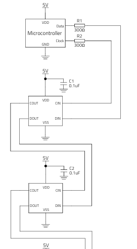
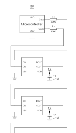
3.1 Model 1311610030140: Chip IC RGB LED Compact

This is 6 pin Chip IC LED with clock and datain , in some specification it is classified asSPI chip IC LED, since clock pin is used. 

Thus 3000ohm resistor shal be used to control leaky current

image

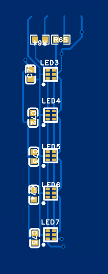
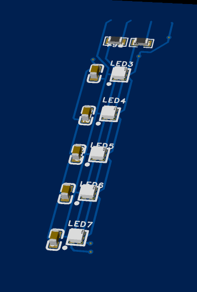
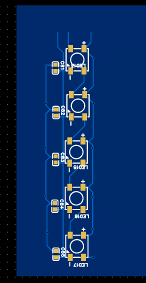
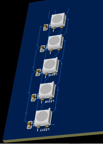
Here is the PCB design with 3D

imageimage

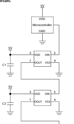
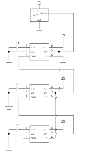
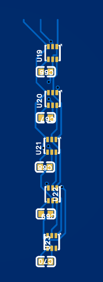
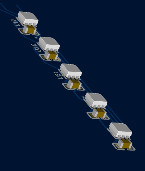
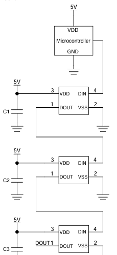
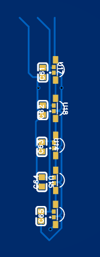
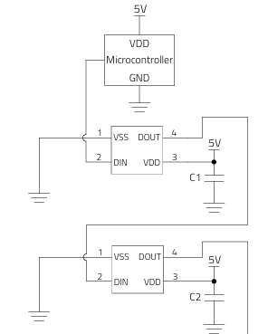
3.2 Model 1312020030000: Chip LED Compact IC RGB

This is simple topography with only DataIn and DataOut pin to control the Chip IC

image

Here is 3D PCB design

imageimage

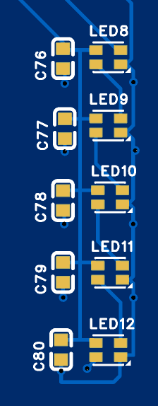
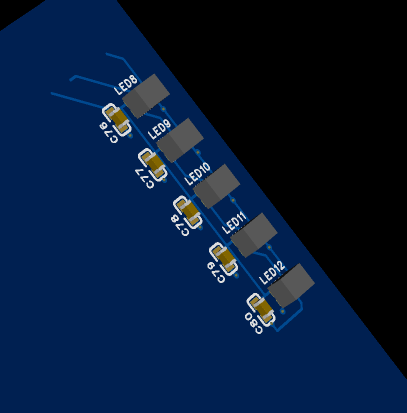
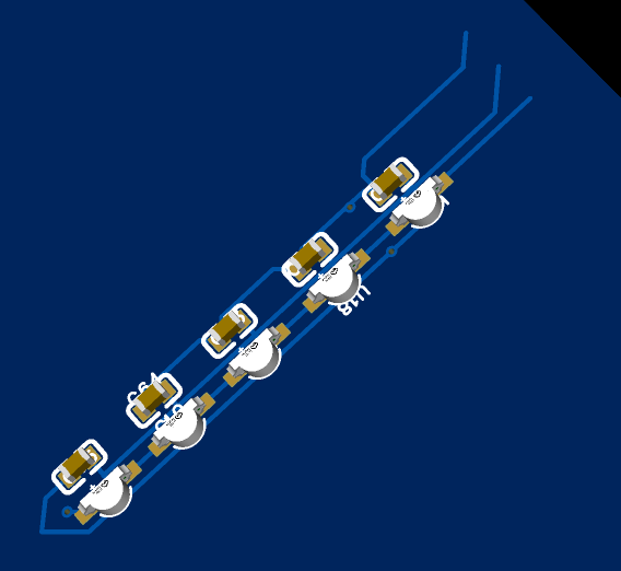
3.3 Model 1312121320437: SMT PLCC6 IC RGB LED

This is one of interesting design, since BI pin is used . The BI pin allows direct bypassing of the controller to turn off LEDs instantly. This give interesting application such as for emergency purpose.

image

Here is the PCB design

imageimage

3.4 Model 1313210530000: Side View IC RGB LED

It appears normal with DataIn and DataOut pin only, but the variation in PAD position give more control over PCB Design

image

PCB design as 

imageimage

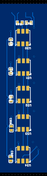
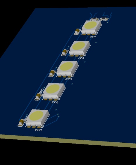
3.5 Model 1315050930002: SMT PLCC4 IC RGB LED

Another typical 4-pin configuration

image

PCB design as 

imageimage

3.6 Model 1315050930246: SMT PLCC6 IC RGB LED

Another 6 pin 

image

PCB design as 

imageimage

4. Summary

Only with deep study can design PCB is possible, there are many engineering technique in the package and pin configuration for various application scenary.

These six WL-IC LED are high niche  among peers.

I shall compare with some normal grade IC LED - WS 2816 in next discuss, and show how the control protocol works.

  • Sign in to reply
  • Cancel
element14 Community

element14 is the first online community specifically for engineers. Connect with your peers and get expert answers to your questions.

  • Members
  • Learn
  • Technologies
  • Challenges & Projects
  • Products
  • Store
  • About Us
  • Feedback & Support
  • FAQs
  • Terms of Use
  • Privacy Policy
  • Legal and Copyright Notices
  • Sitemap
  • Cookies

An Avnet Company © 2025 Premier Farnell Limited. All Rights Reserved.

Premier Farnell Ltd, registered in England and Wales (no 00876412), registered office: Farnell House, Forge Lane, Leeds LS12 2NE.

ICP 备案号 10220084.

Follow element14

  • X
  • Facebook
  • linkedin
  • YouTube