1 Solder method for WL-ICLED
Just briefing the solder method for WL-ICLED with the 4-pin production, 1312020030000, 1313210530000, 1315050930002, since there are still some problems driving 6-pin.But the principle are the same.
The soldering methods include using a soldering iron, hot air gun, and soldering station.
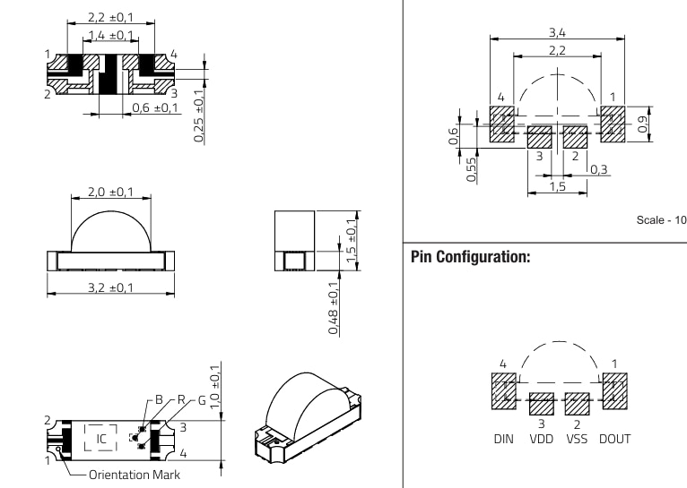
1.1 Characteristics of the LEDs
1.2 Pre-Soldering Preparation
2 Solder iron used for 1315050930002
2.1 Soldering Iron Method (Manual Point-to-Point Soldering)
Soldering Steps
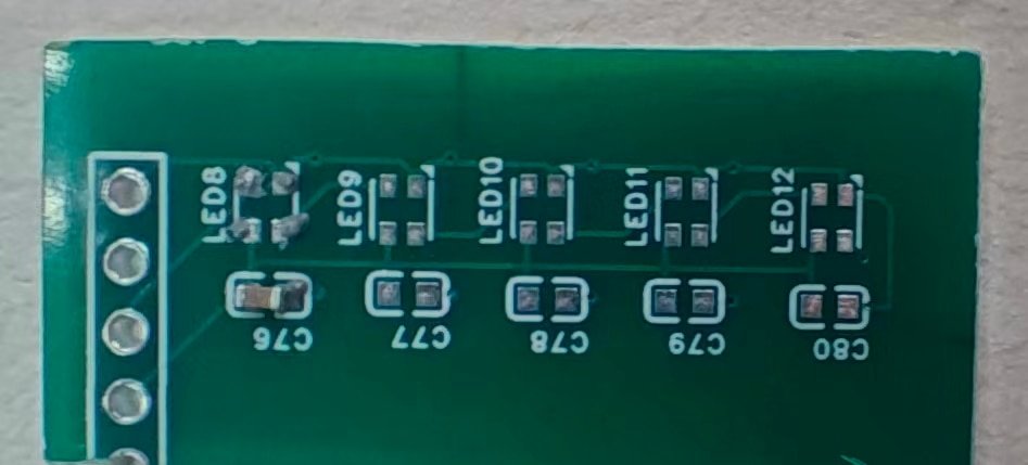
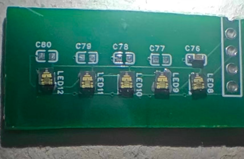
Like this, this is photo for capacitor, same to the 1315050930002.
2.2 Short circuit and bug detection
I am too quick in put everything in place. But it frustrated me with the five WL-ICLED black out. It is liable to overtemperature and break the LED with solder iron. I have to remove them all to check one by one.
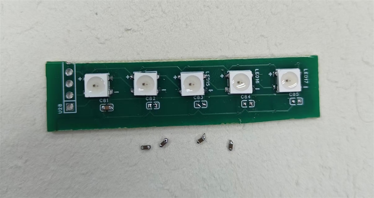
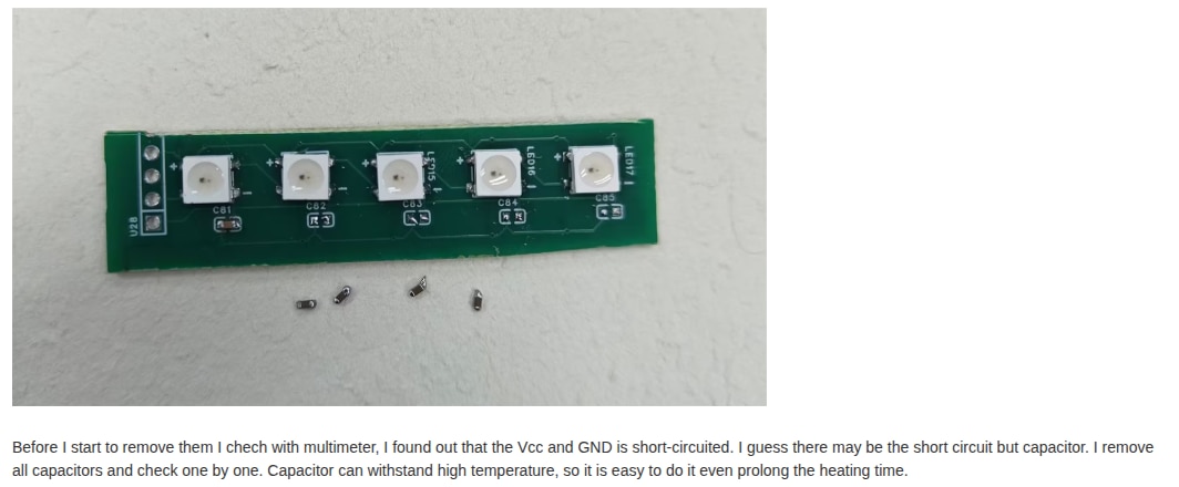
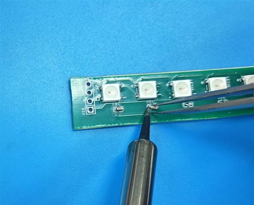
Before I start to remove them I chech with multimeter, I found out that the Vcc and GND is short-circuited. I guess there may be the short circuit but capacitor. I remove all capacitors and check one by one. Capacitor can withstand high temperature, so it is easy to do it even prolong the heating time.
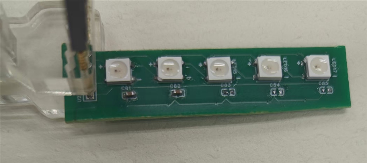
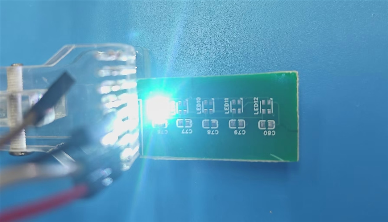
Yes, it works. The solding for LED is OK, save lots of time for me.
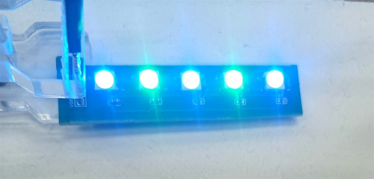
This video shows one bug from software, there are two LED skipped. Only three ones blinks. I shall explain later in next post. That is ineresting foundout. Anyway, solder is Good.
The solder iron is quick and easy to use. Even for smaller parts, that is OK. But temperature control need skill and experience.
| Advantages | Disadvantages |
|---|---|
| 1. Low tool cost (affordable soldering irons under $20), low entry barrier – ideal for small-batch production or repairs. 2. Localized heating minimizes thermal shock to the LED chip (chip temperature ≤200℃, reducing damage risk). 3. Easy solder volume control reduces bridging; high soldering precision (simpler for 4-pin components). 4. No complex equipment debugging – suitable for on-site quick soldering. | 1. Low efficiency (30-60 seconds per component) – unsuitable for mass production. 2. Skill-dependent; beginners may experience cold solder joints (insufficient heating) or dry joints (poor pad wetting). 3. The Side View product 1313210530000 may have obscured pins due to packaging, requiring angle adjustments for visibility. |
I prefer to solder iron in most cases.
3 Solder plate for 1312020030000, 1313210530000
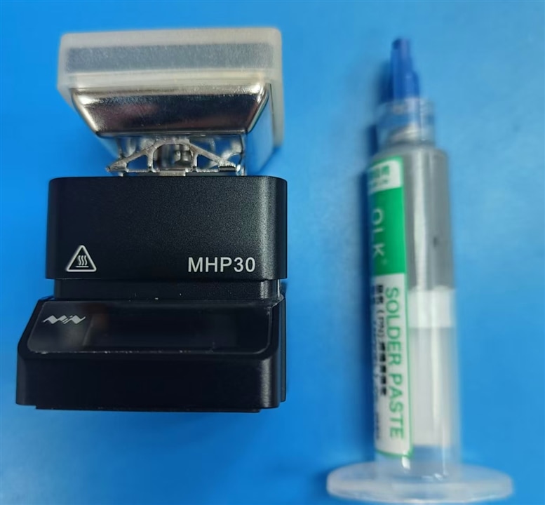
3.1 Solder plate -Soldering Station Method (Temperature-Controlled Platform + Auxiliary Tools – Nearly Professional-Grade Soldering)
It is not difficult to buy one solder plate and solder paste. This is mini-version of solder station, in fact it is just one normal solder plate.
Steps
Since this is small PCB and mini solder plate is enough. Normally steel mesh for LED can be ordered with PCB at the same time. So as to apply the solder paster one time only and evenly without any problems.
In fact, I just dip the solder paste with hand. This lead to low quality in soldering by unevenly distributed solder paster.
3.2 For 1312020030000
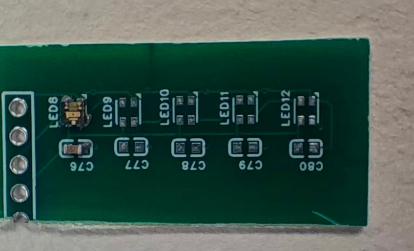
Prepare the PCB and apply solder paste, put first capacitor in place.
Position all the 1313210530000 leds,
no need to worry about the precise position. If the paste applied evenly, the melted paste can pull the led in right position in the end.
It is preferrable to finish one LED first to confirm the polarization
as the video shows,
Then put all others in same manner. But things is not always go easy , the middle one(the 3nd ) led is not blinking .
After visual inspection, I find out that there paste is not evenly applied on all four-pin. So, it is pull off original position and off-load one of the pin.
I use simple solution to fix it. Put it on solder plate and heating again and take off the solder plate and cooling the PCB. AND, press the LED in right position on PCB with a tweezer until it cool down.
3.3 For 1313210530000
This is smallest PCB of all six LEDs, and it is side view LED.
I have made a mistake in PCB design. I select wrong model and the arrangement of PIN pad is different. the PIN pad 2 and 3 shall be in opposition side.
Once I appliy solder paste bit by bit and finish routine solder process, the LED is always black.
What a mistake. I do not have enough time to revise the design and order new PCB again.
I have to use one silly step again. apply minimum solder paste and solder 1313210530000 led one by one. As described above, repositoin the LED with tweezer during cooling down.
And finally, all positioned.
And luckly, all work fine.
3.4 A little summary on to and pro
| Advantages | Disadvantages |
|---|---|
| 1. Precise temperature control (±5℃ error) minimizes thermal shock to the LED chip – highest soldering yield (≥99%). 2. Extremely high efficiency; supports simultaneous soldering of multiple components (e.g., arrays of WL-ICLEDs) – ideal for mass production. 3. Stable soldering quality; eliminates human error for uniform, durable solder joints with strong long-term reliability. 4. Compatible with all three products (Side View 1313210530000 and PLCC4 packages) – no visibility or heating blind spots. | 1. High equipment cost ($200-$1000 for professional stations) – significant initial investment. 2. Requires supporting consumables (solder paste, stencils, clamps) and complex workflows (preheating, temperature control, cooling). 3. Low cost-effectiveness for small-batch production or repairs (time-consuming setup/debugging). |
4 Solder method of hot air gun
This is the most popular choice for all. And high efficiency for refurbishment and repair in all situation.
Here is routine for hot air gun heating,
Soldering Steps
While I skip this choice , since
| Advantages | Disadvantages |
|---|---|
| 1. Uniform heating solders all pins simultaneously – high efficiency suitable for medium-batch production. 2. Lower skill requirement than a soldering iron. | 1. Tool cost something and requires dedicated nozzles. 2. Improper temperature/airflow control may damage the LED chip |
5 Comparation of Solder method
Simple suggesion below
| Soldering Method | Core Advantages | Applicable Scenarios | Not Recommended For |
|---|---|---|---|
| Soldering Iron | Low cost, simple operation, minimal thermal shock | Small-batch production, repairs, DIY | Mass production, Side View packages |
| Hot Air Gun | High efficiency, uniform heating, compatible with Side View packages | Medium-batch production, repairing soldering defects | PCBs with nearby thermosensitive components |
| Soldering Station | Stable quality, high yield, suitable for mass production(Steel mesh needed) | Mass production, high-reliability requirements | Small-batch production, repairs, DIY |
6 Some Hints
6.1 Visual inspection is important
Prepare on mini magnifier with near-view illumination. This is view of1313210530000, the IC-chip and RGB leds is easily read out.
6.2 Software matters, demo code shall be used during solder process.
The clock sequence may affect the one-wire WL-ICLED protocol. The 6-pins WL-ICLED equipped with clock pin, it would be more stable.
6.3 Placement of Capacitor can be re-designed in small PCB. In some PCB, not all capacitor is soldered on. But the LED blink GOOD. In one hand, the WL-ICLED is robust in harsh state. On the other hand, not all capacitor is mandatory.