


This project is extremely complicated given the number of components and power systems and I have never designed a buck booster on a PCB myself. So It took some time to learn and get it done. Add to it, my work required me to travel quite a lot and so, i couldn't post an update. But here I am.
LED Control using Micro-controller
I Immediately soldered the 1315050930246 and 1315050930002 on the Breakout board and wired it to my Nucleo Board. The Nucleo gave me 5V and I routed it's 3.3V logic through the logic level converter from Adafruit which I already had, Guess which chip it used? TXS0108EPWR. I really wanted to use the Fast-LED Library given the amount of effects i can easily do with it based upon its documentation, but behold my bad luck that STM32 code was failing and i had to resort to the Adafruit's Dot-star for DATA + Clock Protocol and Neo-pixel for Single Wire Data protocol.
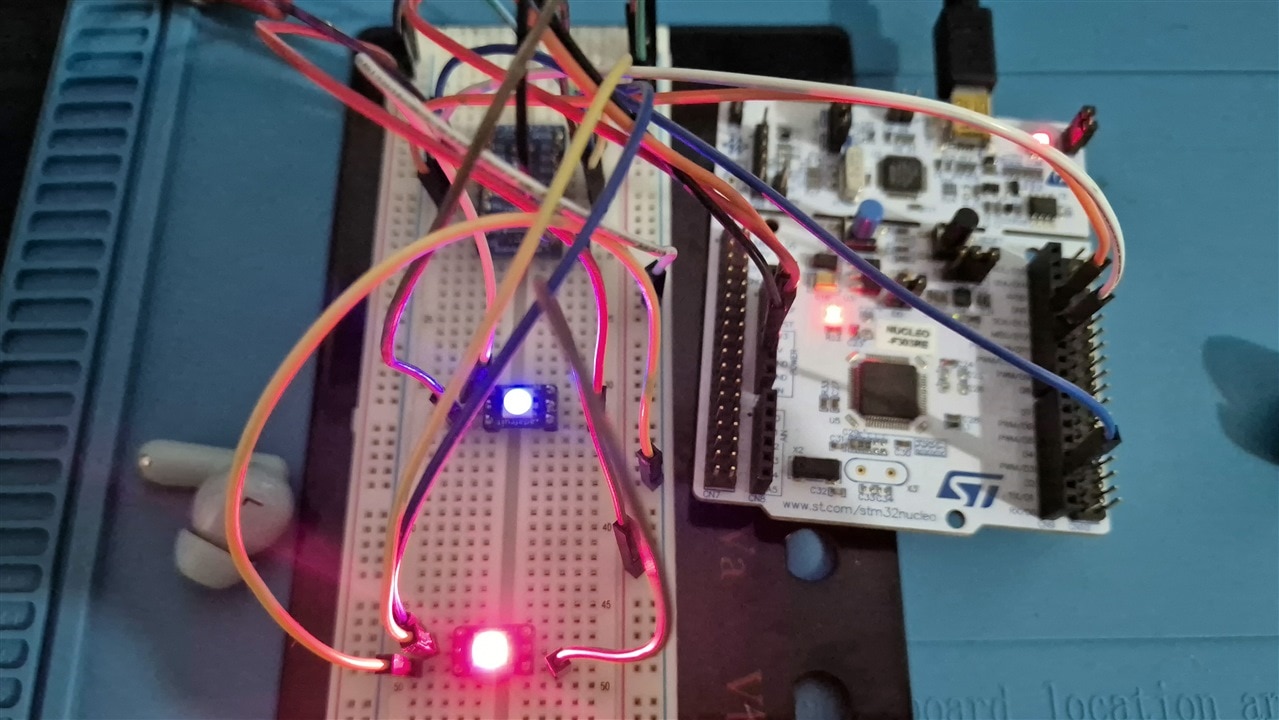
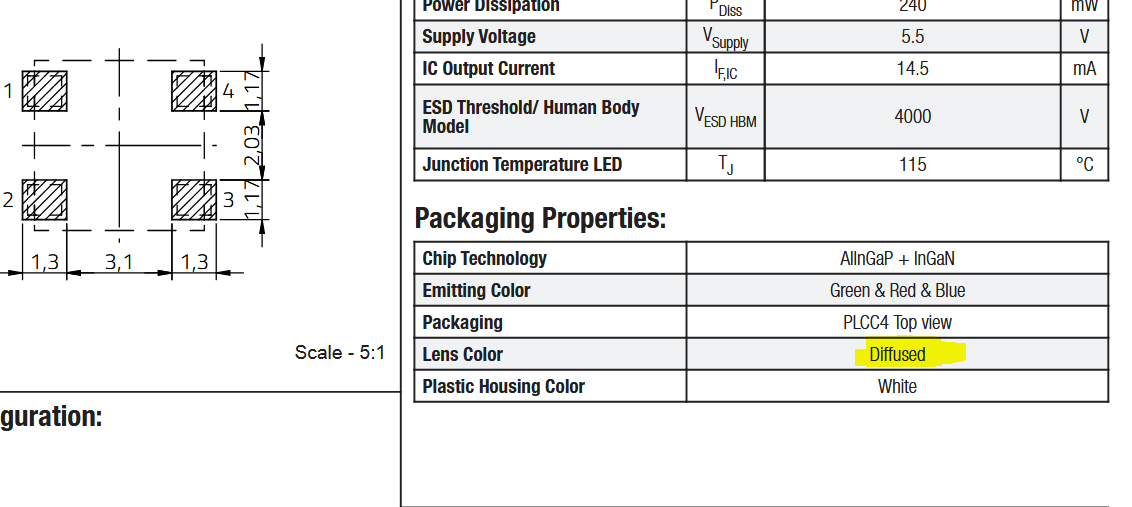
Things i noticed about the Wurth's LED 1315050930002 compared to WS2812B 5050. At the 5V Voltage, brightness is almost imperceptible but as the supply voltage does down, the Wurth's LED gives better Light. Sadly i was not able to capture this on my phone because to try this out, i had to use my university Lab and also Wurth's Plastic enclosure seems to be far more forgiving to my bad soldering skills. I have melted quite a couple of WS2812B 5050 in the past. Now, I have never used an Equivalent of the 1315050930246 so, no comments there. Also I noticed that Wurths' LED is Diffused. Something I overlooked in the Datasheet but it turned out to be a happy mistake because now i need not have a strong diffusion material in my project.
I did the same using the ESP32 Dev Kit (not S3 version) and again, i was able to control it without much change.
The PCB Design
In the Architecture, i mentioned that i plan to use an LiPo Battery which means the supply voltage is gonna vary between 3.4 and 4.2V, and yes, i have been able to make the LED work at lower voltages, but the brightness was not to my liking. A boost converter was needed. After going through the videos https://www.youtube.com/watch?v=QnUhjnbZ0T8 by GreatScott and Phil's Lab's Boost Converter Design & Sizing - Phil's Lab #113 , Switching Regulator PCB Design - Phil's Lab #60 and Boost Converter PCB Design - Phil's Lab #106 i chose the components for the power supply-
- TPS6123 - 5V boost converter to ensure that LED receives 5V always for consistent illumination
- AP61300Z6 - 3.3V Buck converter for the Logic level.
- AP2112K-3.3 - Backup 3.3V
- MCP73831 For battery charging along with FET based power path (A stable circuit Ive been using for an year now)
- Dual Mosfet based Batter's Voltage measurement system
- FUSB303BTMX for USB-PD
- TPS25200 EFuse
I also added an ESP32-S3 and STM21L031, ICS-43434, TXS0108EPWR, NRF24L0. While I was learning the buck boost converter, i also came across Phil's Lab - ESP32 + PCB Antenna Hardware Design Tutorial - Phil's Lab #90 and so went ahead and added in a circuit for NRF24's chip with a PCB Antenna. I am using a Dual MOSFET design, so that i can read the ADC value only on demand and rest of the the time, the Battery is cut-off from the resistor bridge thus avoiding the slow current leakage which will reduce battery life. I thought hard to see if a Couloub based Battery Guage is worth is e.g. bq27441 as seen in Sparkfun baby sitter. But the cost is too high and we do not need very accurate measurements. The component is placed on the PCB such that each subsystem is visually different
Average Boost Converter has an efficiency between 80-90% based on load and many other factors. Assuming 80% efficiency the input current needed for the Boost to 5V = I_in = (V_out * I_out) / (V_in * 0.8).
Now, in the last post i mentioned i needed 250mA for the LEDs. That was for one channel, for all three channels it is 750mA which requires an input current of 1.38A, So input to the Add in ESP32-S3 which needs 500mA for itself as per their documentation and another 100mA for all others, it adds up-to almost 2A peak usage. Therefore, a 15W USB-PD Chip was needed. Note that for hand-held device, it is not needed as it does not have ESP32 and the LED power usage is lower, and most of the time it is supplied from the battery
And for the safety of any computer into which the device may be plugged into, i added an EFuse which will trip off at 2A
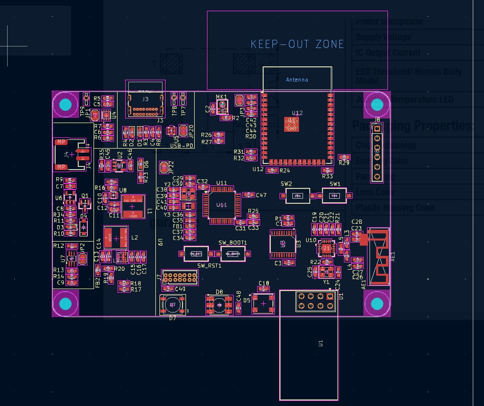
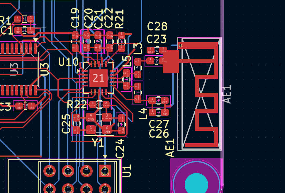
For the PCB Antenna, I had to calculate the micro-strip width to ensure that I get 50Ohm Impedance for a two layer board, KiCad's Calculator told be that i had to use a 2.8mm wide track. I was sure i made some mistake in the input, Kicad's micro-strip calculator had many options, But it turned out to be correct no matter what. The thickness of the dielectric layer played a major role,. and i have to use a 4 Layer board for a practical track width, but i decided to go ahead anyway and take a risk. So at the end of the last passive i drew a track of 2.8mm width to the feed of the antenna. I did add an backup NRF module just in case.
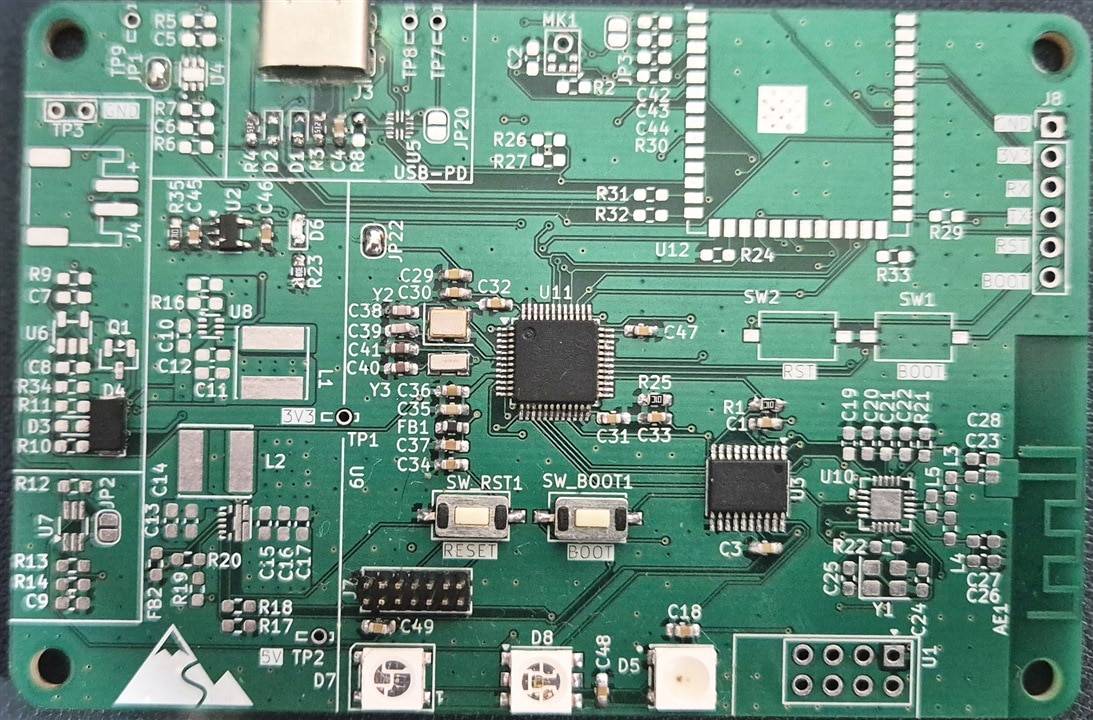
After couple of hours of routing, i sent it to the FAB and within a week i received the boards.
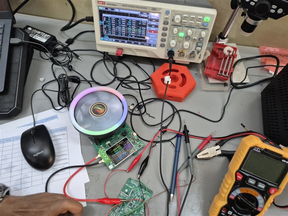
The PCB Testing
I had 5 boards manufactured. To test the circuit in isolated manner, I decided to populate 3 boards each with different systems
Board 1: USB PD, Battery Charger and EFuse.
In this i only populated the USB, Battery Charger and eFuse. I shorted the wires to see if the eFuse will work and yes it turned off the power supply, no harm done. Note that this TPS25200 can be programmed to trip at any particular current value upto 3A by setting the appropriate value of resistor. I first programmed it to trip at 500mA, i connected it to my previous prototype of the hex device which uses WS2812B and monitored the current using Nordic Power Profile Kit V2, and on cue it turned off at around 540mA. For exact 500mA trip, i did not have the right value of Resistor. Next i tried with 2A, and again it worked correctly at around 2A.
Then i added in the ESP32-S3, Microphone and Tested the I2S Interface and a sample Edge Impulse code for keyword spotting and it turned out well.
Disaster Struck. I turned off my oscilloscope which i used to check the ripples in the 5V VBUS and came after lunch and when i turned it on, i see lines on the screen. And over the next few days, the oscilloscope went dead. Now gotta use my university equipment.
Board 2: Buck Converter and Boost Converter
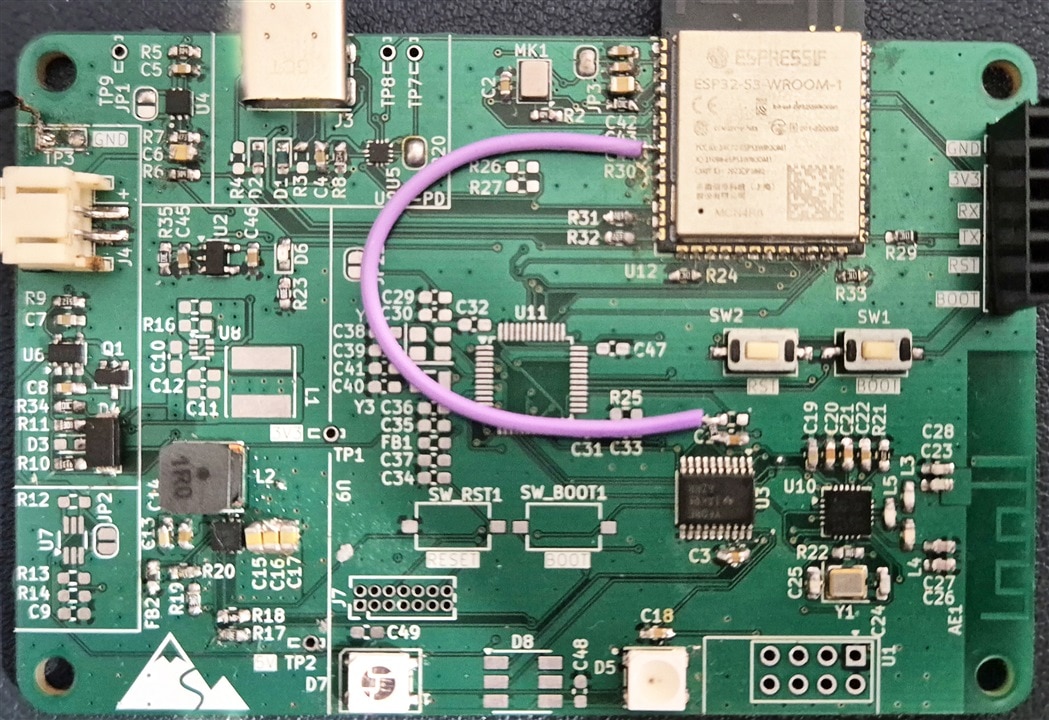
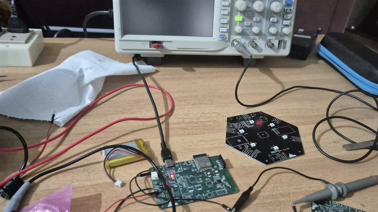
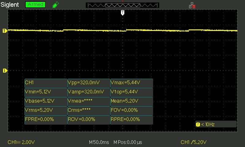
Installing both the boost converter and Buck converter, i hooked it up to a load tester to see how it performs. The ripple was around 320mV peak to peak, which is quite terrible. I tried to replicate the suggested layout in the datasheet, but After scanning through the datasheet i realized i made some mistakes. Oh well, except for a ominous hum at low load, it was fine. I put the boost converter to the board 1 and ran the LED using the esp32, no problem at all. but the 3.3V buck converter was out of the question. Decided to use the LDO in the future for this project. The 5V boost converter is enabled only on demand via micro-controller. The Green Jumper is to tie the enable it by tying it to 3V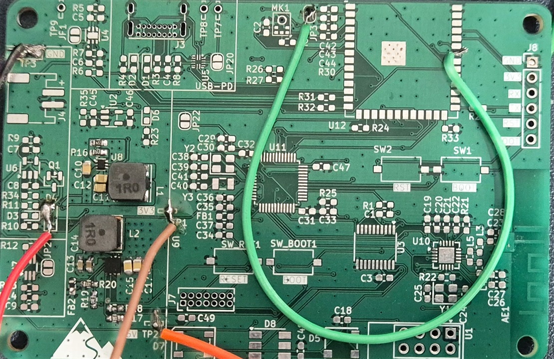
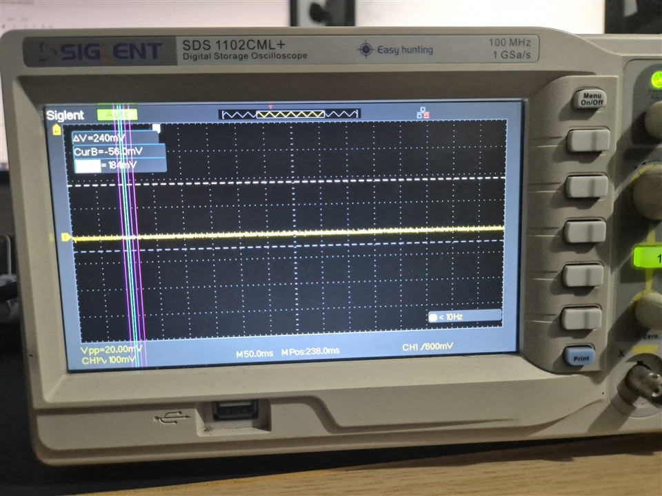
Here is the Waveform for the 5V showing 320mV peak to peak ripple.
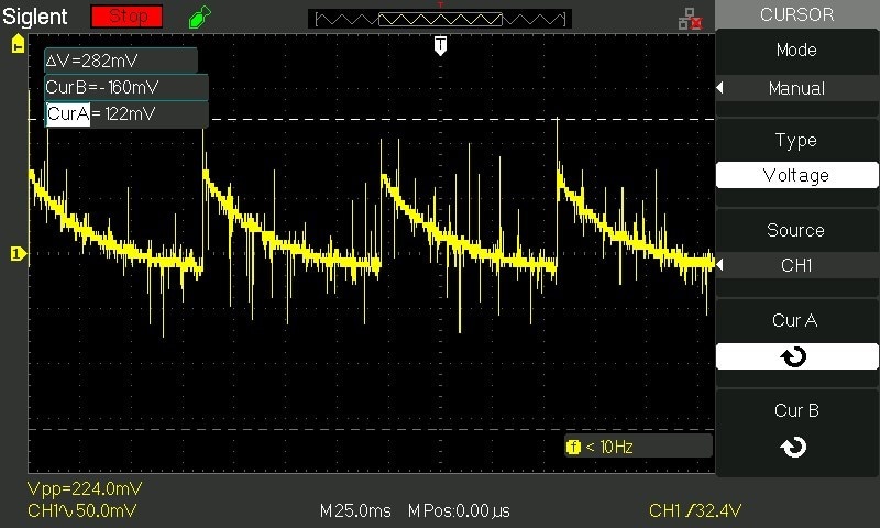
And below is the actual ripple caused by the boost converter.
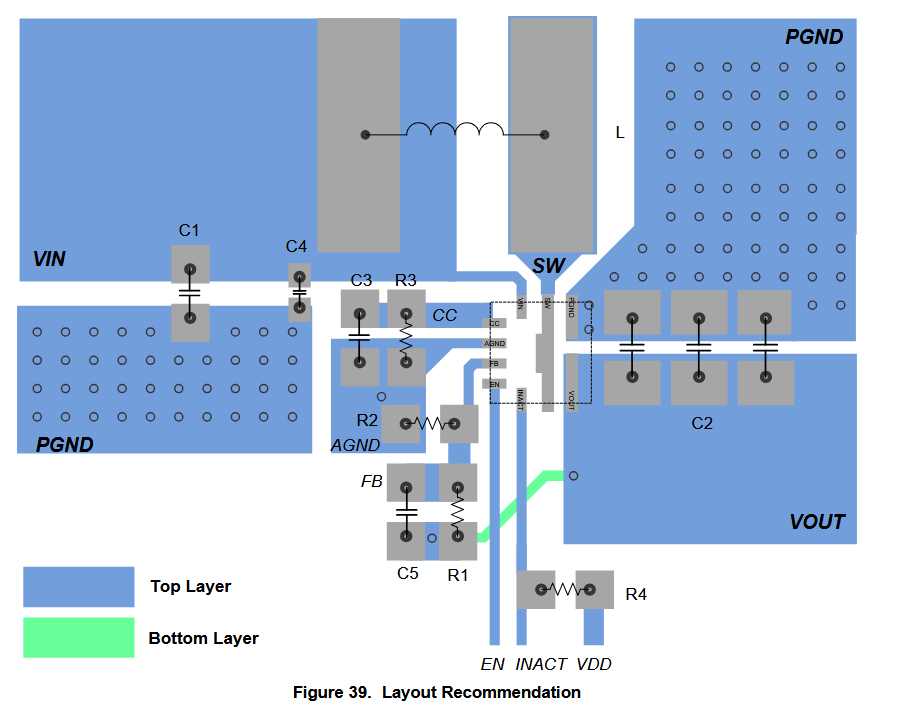
The mistakes i made in the boost converter was
- Poured ground under switching element, it makes ground noisy for sure and theory says it increases EMI
- The Datasheet said i should have only polygon in top layer for switched node, input and output while having ground for input and output. But i put pour on top and bottom and connected them by via. Apparently doing that on switched node makes things worse.
- I should be connecting AGND, PGND to the regular ground via a star point. I did not
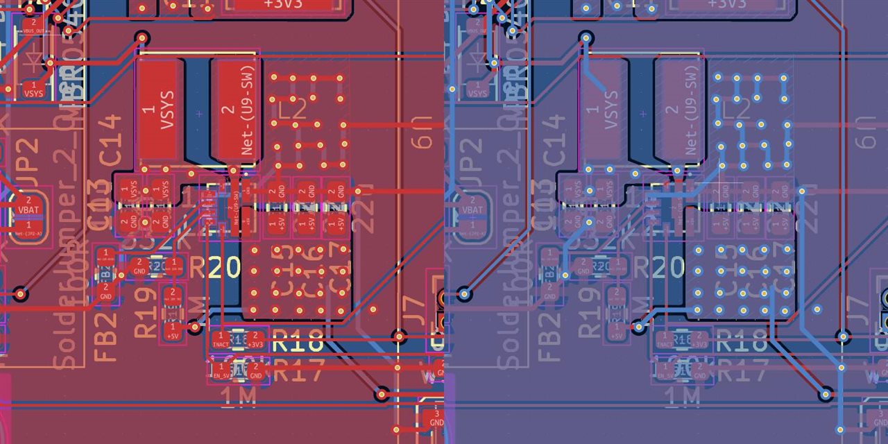
Here is the recommended layout for TPS6123
and the one i did. (Red is top layer, Blue is bottom layer)
Board 3: STM32 and LED
This board will be Powered by USB-C with 5.1K resistor which can give me minimum 500mA, i Soldered on STM32, Logic Level converter and LED's and ran it. All well.
Observations
- The Buck converter is extremely noisy and i do not have the skillet nor time to fix it.
- The Boost converter gives an hum during low load. Not gonna see this during actual usage as LED will pull enough current.
- The Level converter and the on demand 5V does destroy the level converter chip. The datasheet says the Chip has to be enabled via OE pin only after the higher voltage input has been stabilized. So i had to do a patch work on the Board one. It seems if i don't adhere to this rule, the chip does get destroyed.
- The Wurth LED does respond to 3.3V Logic too with 5V Supply. Obviously it works does not mean it will work reliably. Stick to the Digital input voltage - high-level value in the datasheet for reliable communication
Changes to be Made
- Sacrifice efficiency for clean and stable 3.3V by using an LDO
- LED changes based on some further design thinking. Small change in Industrial design also
- Improve the layout of the 5V boost converter by adding an Electrolytic capacitor and fix the layout issue (Put Ground plane under the switching element where i was sup)
Newer Power Budget for LEDs
| Device | Qty | Current per LED Color | Total Current | |
| Nano | 1312121320437 | 3 | 20 | 180.00 |
| 1313210530000 | 12 | 5.5 | 198.00 | |
| Total | 378.00 | |||
| Hex | 1315050930002 | 7 | 13 | 273.00 |
| Total | 273.00 | |||
| Halo | 1311610030140 | 12 | 6 | 216.00 |
| 1315050930002 | 1 | 13 | 39.00 | |
| Total | 255.00 |
Now off to the Final PCB Design ...