1. Original Project Scope
Originally, I'd like to build a low power control system for my existing backup sump pump. I hope my sump pump can work 30% to 50% longer on fully charged batteries when grid electricity is out.
My sump pump is an AC electric pump which is automatically backed up by a CyberPower UPS during a power outage. The built-in battery inside the UPS (CyberPower CP1500PFCLCD PFC Sinewave UPS System) has very limited capacity so I added two external deep cycle lead-acid batteries to extend the working hours. After the addition, the sump pump can work about 10 hours (varying on the rainfall intensity). However, I found the UPS was always in inverting mode even the sump pump didn't kick in. My rough calculation shows it wastes 30% to 50% energy doing nothing. If we can put the UPS into sleep and wake it up when needed, the pump working time can be extended by 30% to 50%. Thus, I'd like to use PSoC 6S2 + AIROC Wi-Fi/Bluetooth Pioneer Kit's low power capability as well as IoT connectivity to design a sump pump monitoring and control system.
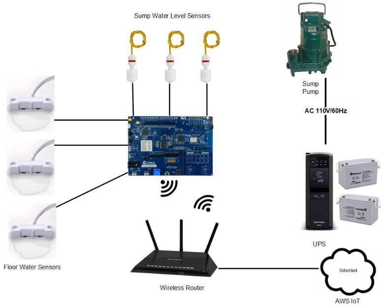
As depicted in the system diagram below, the low power IoT system consists of two sets of water sensors, PSoC 6S2 + AIROC Wi-Fi/Bluetooth Pioneer Kit', UPS with addition batteries, AC sump pump and Wifi router connected to Internet. When the power grid is on, the sump pump is powered by the grid (UPS bypasses the battery power and directly uses grid power). The pioneer kit just monitors the sensor status as well as UPS status through the UART communication. Users can retrieve the real time status online. When power outage occurs, the UPS will power up the sump pump as needed by inverting battery power to AC power. The kit will put the UPS into sleep most of time even it periodically checks the sensor status. Once it detects the water level passing certain threshold level, the kit will wake up UPS and water is pumped out. After the pump stops, the kit will put UPS and itself into sleep again. The kit will sleep most of time and periodically checks the water level to determine if it needs to wake up UPS. It also check the floor to see if there's an overflow in case the pump stops working. If overflow does occur, the kit will send out alarm.

2. Problem with UPS
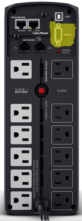
As depicted in the diagram above, I thought the pioneer kit can control the UPS through UART/RS-232 communication. My UPS model is CP1500PFCLCD from CyberPower. On its back panel, it has one USB Type B port and a serial port as shown in the picture below. I connected my PC to the UPS through a USB/RS-232 cable and tried CyberPower's UPS management software PowerPanel. Unfortunately it didn't work. It turns out the serial port (DB9 female connector) isn't actually a serial port. CyberPower only uses a couple of lines to indicate the UPS' basic status such as AC input is OK or not. It seems lots of people realized the similar issue on their own CyberPower UPS models and they were able to add a real serial port through an on-board network extension port. On my case, I couldn't find such port in my UPS model.
Since serial port doesn't work out, I was trying to get a solution with the USB port. The UPS has a USB B connector on its back panel. It kind of indicates it is a USB device rather than USB host. Thus the pioneer kit has to act as a USB host port. Based on PSoC 6 manual, USB port on PSoC 6 can be configured as host, device or OTG port. However, when I tried to find USB host driver software, I ran out of luck. In the PSoC 6 developer forum, there's a USB Host support post which clearly states there's no host driver ready yet.
3. New Project Scope
As explained above, I cannot control my UPS through either serial port or USB port. Thus, I have to change my project plan. Instead of controlling UPS to prolong backup sump pump's working hours and monitoring sump well water level and overflow, I have to limit my project scope to the monitoring functionality. And I have to remove the UART control connection in my original system diagram and it becomes the following diagram.