element14 Community
element14 Community
    Register Log In
  • Site
  • Search
  • Log In Register
  • Community Hub
    Community Hub
    • What's New on element14
    • Feedback and Support
    • Benefits of Membership
    • Personal Blogs
    • Members Area
    • Achievement Levels
  • Learn
    Learn
    • Ask an Expert
    • eBooks
    • element14 presents
    • Learning Center
    • Tech Spotlight
    • STEM Academy
    • Webinars, Training and Events
    • Learning Groups
  • Technologies
    Technologies
    • 3D Printing
    • FPGA
    • Industrial Automation
    • Internet of Things
    • Power & Energy
    • Sensors
    • Technology Groups
  • Challenges & Projects
    Challenges & Projects
    • Design Challenges
    • element14 presents Projects
    • Project14
    • Arduino Projects
    • Raspberry Pi Projects
    • Project Groups
  • Products
    Products
    • Arduino
    • Avnet & Tria Boards Community
    • Dev Tools
    • Manufacturers
    • Multicomp Pro
    • Product Groups
    • Raspberry Pi
    • RoadTests & Reviews
  • About Us
  • Store
    Store
    • Visit Your Store
    • Choose another store...
      • Europe
      •  Austria (German)
      •  Belgium (Dutch, French)
      •  Bulgaria (Bulgarian)
      •  Czech Republic (Czech)
      •  Denmark (Danish)
      •  Estonia (Estonian)
      •  Finland (Finnish)
      •  France (French)
      •  Germany (German)
      •  Hungary (Hungarian)
      •  Ireland
      •  Israel
      •  Italy (Italian)
      •  Latvia (Latvian)
      •  
      •  Lithuania (Lithuanian)
      •  Netherlands (Dutch)
      •  Norway (Norwegian)
      •  Poland (Polish)
      •  Portugal (Portuguese)
      •  Romania (Romanian)
      •  Russia (Russian)
      •  Slovakia (Slovak)
      •  Slovenia (Slovenian)
      •  Spain (Spanish)
      •  Sweden (Swedish)
      •  Switzerland(German, French)
      •  Turkey (Turkish)
      •  United Kingdom
      • Asia Pacific
      •  Australia
      •  China
      •  Hong Kong
      •  India
      • Japan
      •  Korea (Korean)
      •  Malaysia
      •  New Zealand
      •  Philippines
      •  Singapore
      •  Taiwan
      •  Thailand (Thai)
      • Vietnam
      • Americas
      •  Brazil (Portuguese)
      •  Canada
      •  Mexico (Spanish)
      •  United States
      Can't find the country/region you're looking for? Visit our export site or find a local distributor.
  • Translate
  • Profile
  • Settings
Make Life Accessible
  • Challenges & Projects
  • Design Challenges
  • Make Life Accessible
  • More
  • Cancel
Make Life Accessible
Blog Make Life Accessible - Clear Walk Motor Gearing - blog 10
  • Blog
  • Forum
  • Documents
  • Polls
  • Files
  • Mentions
  • Sub-Groups
  • Tags
  • More
  • Cancel
  • New
  • Share
  • More
  • Cancel
Group Actions
  • Group RSS
  • More
  • Cancel
Engagement
  • Author Author: dougw
  • Date Created: 5 Jun 2016 11:42 PM Date Created
  • Views 720 views
  • Likes 4 likes
  • Comments 5 comments
  • accessibility_projects
  • make_life_accessible
  • mla
  • clear_walk
Related
Recommended

Make Life Accessible - Clear Walk Motor Gearing - blog 10

dougw
dougw
5 Jun 2016

I have been spending entirely too much time trying to get the drive train to be functional, but I still need to devote some time to describing what I have been up to. The Linix motor is great - lots of power, but it runs between 300 and 4000 rpm. I need this speed to be reduced by a factor of about 4000 to get reasonable control and accuracy in my solar tracking application.

There are nice gearboxes (like the one below) made for this particular motor, but I cannot afford them:

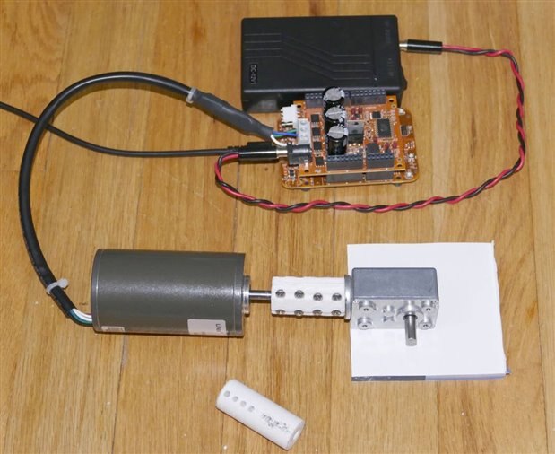
I explored a lot of options as this can be an expensive aspect of the system. I procured several adpters, flex-couplers and gearboxes, to try to cobble a workable combination together, but every component in the system has its own set of problems, each of which requires time and usually money to resolve. The picture below shows a gearbox I obtained by butchering a perfectly good gearmotor, but of course the gearbox driveshaft is a different diameter from the motor driveshaft, so an adapter is needed. The commercial coupler I ordered has not arrived and might not arrive in time for this project, so I have been attempting to make a suitable coupler. The unconnected cyclindrical coupler in the picture caused huge vibration because it could not maintain accurate axial alignment. The clamping coupler shown connected, was a little better, but still not good enough. I hind sight, butchering the gearmotor the way I did was not the best solution. It left only a single bushing in the gearbox to control the driveshaft. And of course I bent the driveshaft a bit in the process - very difficult to straighten accurately.image

It appears that I cannot hold tolerances accurately enough to avoid significant vibration, so I will have to try some kind of very flexible coupling. I expect that will take a few more hours and probably several iterations.

One other nasty issue is that all the nice dimensioned drawings of the gearbox do not show the exact location of the input driveshaft (because it is internal to the gearmotor) and it is not in the middle either vertically or horizontally. Which is going to make building a chassis a tricky problem.

image

The gearbox has a ratio of about 266:1 which is a good reduction but it is not quite enough - it still leaves the output shaft rotating at over 6 degrees per second. My plan is to put a pulley on the output shaft that will reduce the speed by 14:1. This will get the speed down to about 1 degree every 2 seconds. The sun is progressing much slower at about 1 degree every 4 minutes, so the motor only needs to run 0.2% of the time to keep up.

This image shows part of the pulley - I expect to use a separate take-up reel. The 2 clamps will be used to mount the reels to what is left of the handlebars described in earlier blogs. You can see the convoluted threading path for the belt internal to the reel. This is a very tight fit and does a good job preventing the belt from slipping. The aluminum drive sprocket is also shown in the picture just to get an idea of the gear ratio.image


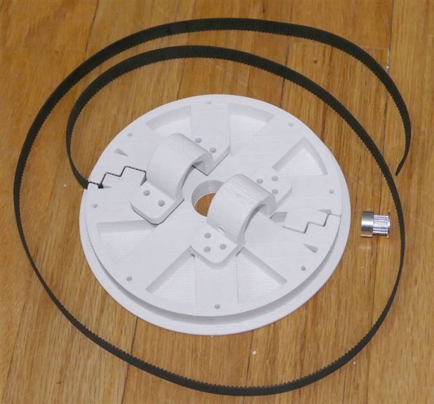
The project is proceeding too slowly despite putting a lot of hours into it, however I am learning a lot about what not to do. Some things like the pulley look like they will work on the first try while others such as the shaft coupler look like they will take many iterations. The drivetrain chassis is definitely going to be difficult.


Relevant Links

MLA Design Challenge


The full set of Clear Walk project blogs can be found here:

Make Life Accessible

  • Sign in to reply

Top Comments

  • jw0752
    jw0752 over 9 years ago +1
    Hi Doug, I have dealt with gear motors and position sensor systems in dental chairs. These actuators use a worm drive off the motor shaft which turns a jack screw actuator. The motion can be very slow…
  • jw0752
    jw0752 over 9 years ago in reply to dougw +1
    I wish you were closer. Son, Matt, must have a hundred used ones sitting on the shelves at the shop. John
  • rsc
    rsc over 9 years ago +1
    Hi Doug, I'm having the same problem with gearing. I will probably end up using some sort of belt drive also. Scott
  • mcb1
    mcb1 over 9 years ago

    Doug

    You may be able to 3D print a simple flexible coupler.

    Automotive steering shafts often use a simple rubber 'donut' with the shaft fixed to a tee piece that is bolted onto the rubber.

    They are arranged 90 degrees to each other so that any misalignment is compensated for.


    Image result for flexible steering shaft joint


    Mark

    • Cancel
    • Vote Up +1 Vote Down
    • Sign in to reply
    • More
    • Cancel
  • rsc
    rsc over 9 years ago

    Hi Doug,

    I'm having the same problem with gearing.  I will probably end up using some sort of belt drive also.

    Scott

    • Cancel
    • Vote Up +1 Vote Down
    • Sign in to reply
    • More
    • Cancel
  • jw0752
    jw0752 over 9 years ago in reply to dougw

    I wish you were closer. Son, Matt, must have a hundred used ones sitting on the shelves at the shop.

    John

    • Cancel
    • Vote Up +1 Vote Down
    • Sign in to reply
    • More
    • Cancel
  • dougw
    dougw over 9 years ago in reply to jw0752

    Hi John,

    I have used jacktuators in the past - definitely strong enough. New ones are costly, but maybe there are used ones out there. Thanks for the tip. Worm gears are great for applications like this - usually you can turn the motor off and they won't move regardless of foces applied.

    • Cancel
    • Vote Up 0 Vote Down
    • Sign in to reply
    • More
    • Cancel
  • jw0752
    jw0752 over 9 years ago

    Hi Doug,

    I have dealt with gear motors and position sensor systems in dental chairs. These actuators use a worm drive off the motor shaft which turns a jack screw actuator. The motion can be very slow and position controlled. The motors are AC bidirectional and are usually controlled with triacs. Sensors are usually linear or rotary potentiometers. I do not know if this technology would be of any help to you but is you have a local dental equipment repair shop or person a trip to their parts graveyard might be of help.

    John

    • Cancel
    • Vote Up +1 Vote Down
    • Sign in to reply
    • More
    • Cancel
element14 Community

element14 is the first online community specifically for engineers. Connect with your peers and get expert answers to your questions.

  • Members
  • Learn
  • Technologies
  • Challenges & Projects
  • Products
  • Store
  • About Us
  • Feedback & Support
  • FAQs
  • Terms of Use
  • Privacy Policy
  • Legal and Copyright Notices
  • Sitemap
  • Cookies

An Avnet Company © 2025 Premier Farnell Limited. All Rights Reserved.

Premier Farnell Ltd, registered in England and Wales (no 00876412), registered office: Farnell House, Forge Lane, Leeds LS12 2NE.

ICP 备案号 10220084.

Follow element14

  • X
  • Facebook
  • linkedin
  • YouTube