element14 Community
element14 Community
    Register Log In
  • Site
  • Search
  • Log In Register
  • Community Hub
    Community Hub
    • What's New on element14
    • Feedback and Support
    • Benefits of Membership
    • Personal Blogs
    • Members Area
    • Achievement Levels
  • Learn
    Learn
    • Ask an Expert
    • eBooks
    • element14 presents
    • Learning Center
    • Tech Spotlight
    • STEM Academy
    • Webinars, Training and Events
    • Learning Groups
  • Technologies
    Technologies
    • 3D Printing
    • FPGA
    • Industrial Automation
    • Internet of Things
    • Power & Energy
    • Sensors
    • Technology Groups
  • Challenges & Projects
    Challenges & Projects
    • Design Challenges
    • element14 presents Projects
    • Project14
    • Arduino Projects
    • Raspberry Pi Projects
    • Project Groups
  • Products & Partners
    Products & Partners
    • Arduino
    • Avnet & Tria Boards Community
    • Dev Tools
    • Manufacturers
    • Multicomp Pro
    • Product Groups
    • Raspberry Pi
    • RoadTests & Reviews
  • About Us
    About the element14 Community
  • Store
    Store
    • Visit Your Store
    • Choose another store...
      • Europe
      •  Austria (German)
      •  Belgium (Dutch, French)
      •  Bulgaria (Bulgarian)
      •  Czech Republic (Czech)
      •  Denmark (Danish)
      •  Estonia (Estonian)
      •  Finland (Finnish)
      •  France (French)
      •  Germany (German)
      •  Hungary (Hungarian)
      •  Ireland
      •  Israel
      •  Italy (Italian)
      •  Latvia (Latvian)
      •  
      •  Lithuania (Lithuanian)
      •  Netherlands (Dutch)
      •  Norway (Norwegian)
      •  Poland (Polish)
      •  Portugal (Portuguese)
      •  Romania (Romanian)
      •  Russia (Russian)
      •  Slovakia (Slovak)
      •  Slovenia (Slovenian)
      •  Spain (Spanish)
      •  Sweden (Swedish)
      •  Switzerland(German, French)
      •  Turkey (Turkish)
      •  United Kingdom
      • Asia Pacific
      •  Australia
      •  China
      •  Hong Kong
      •  India
      •  Japan
      •  Korea (Korean)
      •  Malaysia
      •  New Zealand
      •  Philippines
      •  Singapore
      •  Taiwan
      •  Thailand (Thai)
      •  Vietnam
      • Americas
      •  Brazil (Portuguese)
      •  Canada
      •  Mexico (Spanish)
      •  United States
      Can't find the country/region you're looking for? Visit our export site or find a local distributor.
  • Translate
  • Profile
  • Settings
My Project Is Trash
  • Challenges & Projects
  • Design Challenges
  • My Project Is Trash
  • More
  • Cancel
My Project Is Trash
Forum Tiltie - 01: Introduction and the Road to the Smart Tilting Bin
  • News
  • Forum
  • Projects
  • DC
  • Leaderboard
  • Files
  • Members
  • More
  • Cancel
  • New
Join My Project Is Trash to participate - click to join for free!
Actions
  • Share
  • More
  • Cancel
Forum Thread Details
  • Replies 2 replies
  • Subscribers 2 subscribers
  • Views 36 views
  • Users 0 members are here
  • my-project-is-trash
  • forum-updates
  • design-challenge
  • tiltie
  • smart-tilting-bin
Related

Tiltie - 01: Introduction and the Road to the Smart Tilting Bin

javagoza
javagoza 8 hours ago

I have been selected as one of the official participants in the My Project Is Trash challenge hosted by the Element14 community. This is my first post while I wait for the challenge kit, which is already on its way. I would like to take this opportunity to share my proposal and the path that led me to it. I hope you find it interesting and that it inspires a few ideas of your own.

For those who don't know me, I'm a Spanish developer with more than 40 years of experience and a background in industrial engineering, specializing in robotics, electronics, and automatic control systems. My professional career has mainly focused on software development and solutions for payment systems and access control.

I've always been curious about the maker world, and over the last decade I've occasionally participated in the Element14 community, sharing projects that combine microcontrollers, sensors and actuators, analog electronics, and FPGAs. You can find some of those projects in this summary: My element14community Story

My Motivation for Joining This Design Challenge

The main reason is simply to take a break from work and have some fun. I'm fortunate that my whole family usually gets involved in one way or another with these projects.

Recycling small household and office waste is also a topic that concerns me. I know this project is not going to solve the problem, but it may help illustrate some of the challenges involved in waste sorting and classification.

Evaluating Different Ideas

Before settling on a final proposal, I explored several ideas to determine which would be the most interesting, practical, and enjoyable to build.

Below is a summary of some of them, along with their first designs, presented in the same order in which they originally appeared. Every time I worked on one of these concepts, I was convinced I had found the winning idea, until I procrastinated and became distracted by a new one.

Looking back through my notes now, I realize I would still enjoy building all of them. I wouldn't rule out revisiting some of these ideas in the future.

In previous challenges, I used FreeCAD to create the first sketches of my prototypes. This time, I decided to use OpenSCAD, which allows me to create fully parametric designs through code.

Anyway, here are some of those ideas:

Electromechanical Eco-Pinball

I considered building a portable interactive game inside the Hammond enclosure, controlled through gestures using the IR Light Angle Sensor, small impacts detected by the 3-Axis MEMS Accelerometer, bumper switches based on the CamdenBoss CSM40500A Microswitch, and plenty of illuminated indicators using CamdenBoss Panel Mount Indicators.

The goal was to promote environmental awareness and proper waste sorting through gamification. Pinball machines are always fun, and I liked the idea of turning the Hammond enclosure into a miniature pinball machine.

Top view of the inclined pinball playfield.

image1

Interior cross-section of the pinball.

image2

Sorting Game

Following the pinball idea, the next design evolved into a sorting game built inside the enclosure itself. Players would sort different types of waste, represented by balls, using gestures detected by the ADI IR sensor.

image3

Internal view showing the LEDs and CamdenBoss push buttons.

image4

The next step was a refined version of this game.
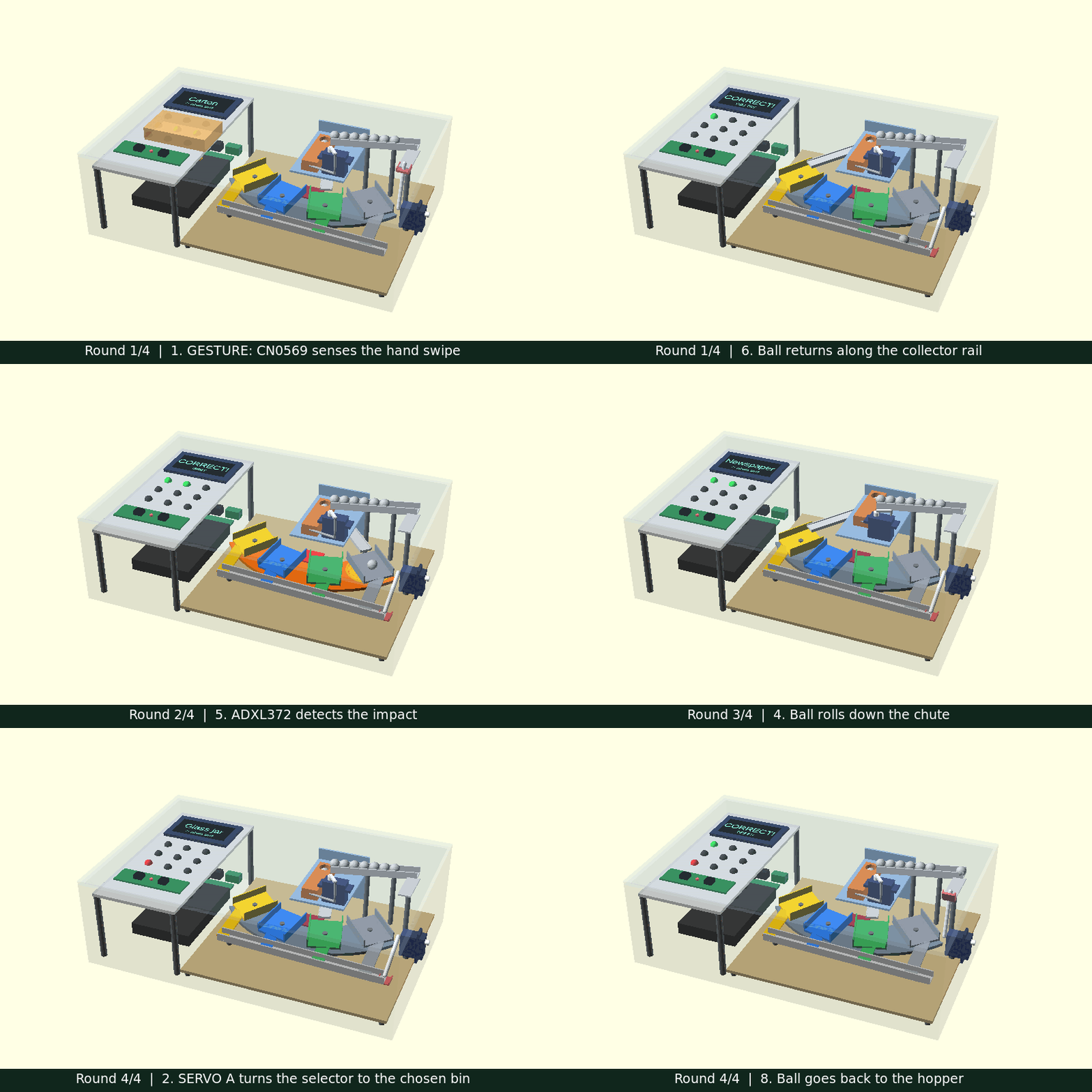
image

Recycling Plant Cranes

After several iterations focused on educational games inside the enclosure, my attention shifted toward another aspect of waste sorting: the cranes used in recycling plants.

The idea was to build an electromechanical system capable of picking up small objects and moving them into different sorting areas, reproducing on a small scale some of the processes used in real industrial facilities.

My first design was a simple polar crane using two motors, with the switches acting as limit switches and homing sensors. It could be used either as a game or as an automatic sorting system.

image

Later, I explored a more visually appealing design based on cables and pulleys driven by stepper motors. The goal was to create a lightweight and relatively simple mechanism capable of positioning a gripper anywhere within the work area.

The first prototype used three motors, but I wasn't satisfied with the available workspace.

image

Adding a fourth motor increased the workspace, but positioning accuracy depended heavily on cable tension and system calibration, making both the control software and the mechanical construction more complex. I was also concerned about the complexity of the gripper itself.

image

My next idea was a Cartesian system with linear guides inspired by 3D printers and CNC machines.

This solution was much easier to control, but it exceeded the budget and was starting to drift away from my idea of what a "trash project" should be.

image

The overall concept remained the same: an educational electromechanical game showing how waste is handled and classified inside a recycling plant.

I kept getting stuck when designing the gripper mechanism. At some point, I realized I could avoid using a gripper altogether by letting gravity do the work. That triggered a small chain reaction in my brain, and the idea for my final proposal appeared: the Smart Tilting Bin.

Project Proposal: Smart Tilting Bin

My proposal is a smart bin for small office waste, built mainly from reused household materials such as bowls, tubes, food containers, scrap wood, discarded cables, and bottle caps, combined with electronic components, sensor fusion techniques, and artificial intelligence.

image

Here's a brief overview of how it works:

1. Multimodal Detection

A camera mounted above the bin observes the object being inserted, while a microphone captures its impact sound and the ADI 3-Axis MEMS Accelerometer records a vibration signature to help resolve ambiguous cases.

image10

2. The Mechanism

A circular concave tray with two cut-outs along its edge acts as a seesaw. It tilts by 45° and rotates by 90° to direct waste into four surrounding bins (packaging, paper, organic waste, and general waste), using only two small motors, including a stepper motor and a homing system based on a CamdenBoss CSM40500A Microswitch.

image11

3. Active Learning Through Gesture Correction

If the AI confidence level is low, the user can simply wave a hand over an infrared gesture sensor (Analog Devices CN0569 IR Light Angle Sensor) to correct the classification. This immediately generates labelled training data for future improvements.

image13

4. Game Mode

A display and several CamdenBoss Panel Mount Indicators provide a built-in guessing game, while an industrial-grade accelerometer protects the device against vandalism or excessively heavy objects.

image14 image15 image16

5. Protection and Control

The AI processing hardware will be protected inside a Hammond 1554X2GYCL Polycarbonate Enclosure IP68, which will also house the electronics responsible for controlling and coordinating the mechanical system.

image17

Wiring between sensors, actuators, and control electronics will use CamdenBoss CTBP93HD/4 and CTBP92HD/4 terminal blocks, making the system easier to assemble, test, and maintain.

image18 image19

Meet Tiltie

One last introduction: meet Tiltie, a magpie and the unofficial mascot of this project. Magpies have a reputation for being smart, curious, and a little mischievous, so the name felt like a good fit. Tiltie will be keeping an eye on the project as it progresses. And if time allows, Tiltie might even make a special appearance in a future update.

image

What's Next?

While waiting for the free kit to arrive, including evaluation boards and hardware from Analog Devices, Hammond, and CamdenBoss, I am finishing the CAD design and preparing the software environment on a Raspberry Pi CM4 and a Raspberry Pi Pico.

In my next updates, I'll unbox the kit, test the sensors, and start building the physical prototype.

Thanks for reading!

  • Sign in to reply
  • Cancel

Top Replies

  • javagoza
    javagoza 3 hours ago in reply to obones +1
    Thanks! Having spent most of my life developing software, OpenSCAD feels more natural to me. What I like most about it is that every dimension can be defined as a variable, and dimensions can depend…
Parents
  • obones
    obones 3 hours ago

    That looks impressive!

    I see you moved from FreeCAD to OpenSCAD so that you write code to create those renderings. What made you decide to change?

    I mean, I started my CAD life with Solidworks, only to move to FreeCAD when I ran out of the student licence, and I can't imagine not seeing what I'm designing while I design it, so I'm very interested on your reasoning here. For the parameterization, I always use a spreadsheet with the values, so I don't have to go everywhere to just change a value.

    • Cancel
    • Vote Up 0 Vote Down
    • Sign in to reply
    • Cancel
  • javagoza
    javagoza 3 hours ago in reply to obones

    Thanks! Having spent most of my life developing software, OpenSCAD feels more natural to me.

    What I like most about it is that every dimension can be defined as a variable, and dimensions can depend on each other. Changing things like hole diameters, wall thicknesses, or objects spacing is often just a matter of editing a single line.

    Since the files are plain-text scripts, they fit perfectly into my workflow. I can version them with Git, review diffs, and manage changes exactly the same way I do with source code.

    Another big advantage is the ability to use loops, mathematical functions, and conditional logic to generate geometry and even simulate physical relationships. For projects with repeated patterns or highly parametric parts, I often find this much faster than manually recreating or editing features.

    You can even leverage LLMs to help create modules or implement certain physical models. Since everything is text-based, they work surprisingly well for that kind of task.

    OpenSCAD also allows you to create reusable modules and build a small library of components that can be shared across different projects, much like software libraries.

    On top of that, OpenSCAD can run headlessly from the command line. For example, I've used it to automatically generate render sequences and animations.

    I completely understand your point of view, though. I have nothing against FreeCAD. It's a fantastic tool, but because of my programming background there are some things that simply feel easier and more intuitive to me in OpenSCAD.

    • Cancel
    • Vote Up +1 Vote Down
    • Sign in to reply
    • Cancel
Reply
  • javagoza
    javagoza 3 hours ago in reply to obones

    Thanks! Having spent most of my life developing software, OpenSCAD feels more natural to me.

    What I like most about it is that every dimension can be defined as a variable, and dimensions can depend on each other. Changing things like hole diameters, wall thicknesses, or objects spacing is often just a matter of editing a single line.

    Since the files are plain-text scripts, they fit perfectly into my workflow. I can version them with Git, review diffs, and manage changes exactly the same way I do with source code.

    Another big advantage is the ability to use loops, mathematical functions, and conditional logic to generate geometry and even simulate physical relationships. For projects with repeated patterns or highly parametric parts, I often find this much faster than manually recreating or editing features.

    You can even leverage LLMs to help create modules or implement certain physical models. Since everything is text-based, they work surprisingly well for that kind of task.

    OpenSCAD also allows you to create reusable modules and build a small library of components that can be shared across different projects, much like software libraries.

    On top of that, OpenSCAD can run headlessly from the command line. For example, I've used it to automatically generate render sequences and animations.

    I completely understand your point of view, though. I have nothing against FreeCAD. It's a fantastic tool, but because of my programming background there are some things that simply feel easier and more intuitive to me in OpenSCAD.

    • Cancel
    • Vote Up +1 Vote Down
    • Sign in to reply
    • Cancel
Children
No Data
element14 Community

element14 is the first online community specifically for engineers. Connect with your peers and get expert answers to your questions.

  • Members
  • Learn
  • Technologies
  • Challenges & Projects
  • Products
  • Store
  • About Us
  • Feedback & Support
  • FAQs
  • Terms of Use
  • Privacy Policy
  • Legal and Copyright Notices
  • Sitemap
  • Cookies

An Avnet Company © 2026 Premier Farnell Limited. All Rights Reserved.

Premier Farnell Ltd, registered in England and Wales (no 00876412), registered office: Farnell House, Forge Lane, Leeds LS12 2NE.

Follow element14

  • X
  • Facebook
  • linkedin
  • YouTube