


In my previous posts I explained the idea behind Knock Knock Sort, I did some simulations of the gate plate and I opened the challengers kit. The argument of this post is the mechanics: how the bin moves each item from the plate where it is "listened" to the right bin. I changed my mind more than once, so I want to show you also the designs I threw away.
Due to time constraints, I am going to create any testbed, but I am going build a prototype that resembles the final product and run all the tests on that. There is another reason for this choice: the real plate may resonate differently depending on how it is mounted, so I believe it's better to collect data on the final hardware.
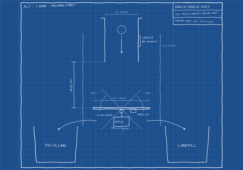
The first idea: a tray that tilts
My first design was very simple. The item falls on an aluminium tray, the tray stays still while the ADXL372 and the microphone record the knock, and then one servo tilts the tray 45° to the left (recycling) or to the right (landfill). The surface that listens is the same surface that sorts, so there is only one moving part, and I liked this a lot.
The problem is that you can select between two sides. With three or four bins I had to add a flap on each side, or split the floor in four trapdoors. The trapdoor version is not feasible: every hinge and every seam is a place where the vibration is lost, so the knock arrives to the sensor in a different way depending from which panel the item hits.
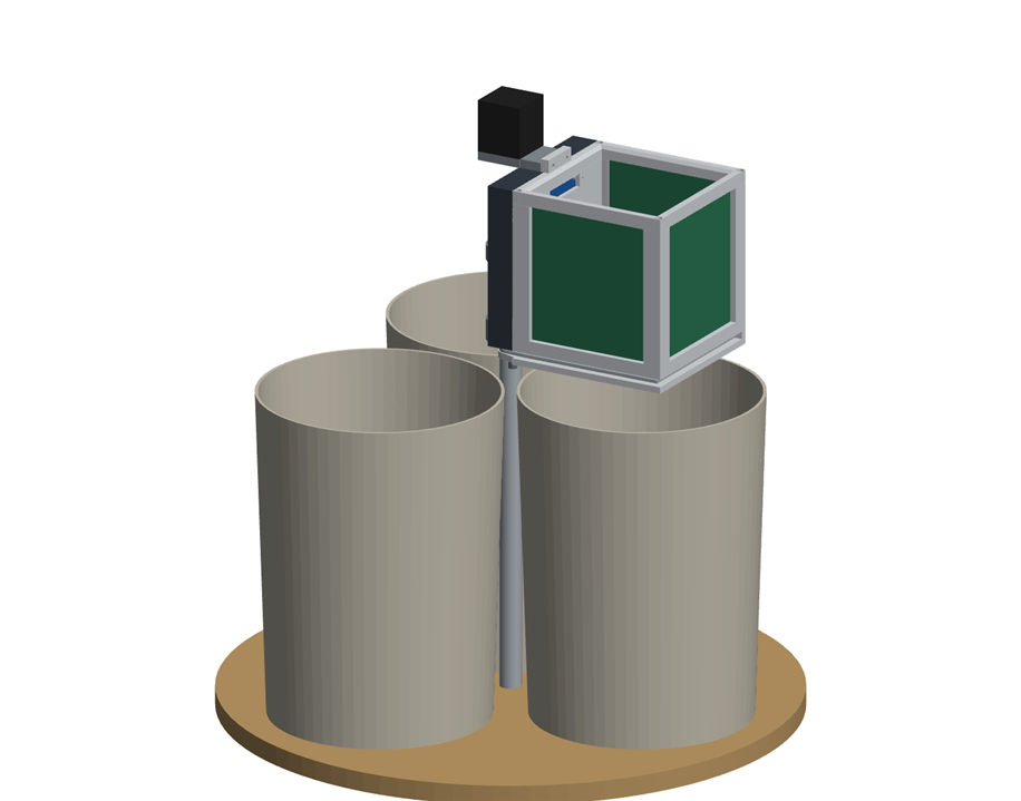
One chute, three bins
So I turned the problem upside down: instead of moving the floor towards the bins, I move the whole chute over the bin. The chute rides on a fixed central pole, a stepper motor turns it over the right bin, and the bottom of the chute is a single aluminium plate that slides to let the item fall. In this way the floor is always one rigid plate, it is always hit from the same height, and nothing moves while the system is listening. Adding a bin only needs a new angle in the configuration file.
The three bins stand 120° apart. The chute never makes a full turn: it moves at most 120° to each side of the home position, so the cables going up the pole never twist.
The first version of the rotating chute had most of the electronics (except the sensors) in the Hammond box located at the base. Sensors were screwed on the chute wall facing the pole, behind a printed cover, and printed clamps hold the chute to the pole.
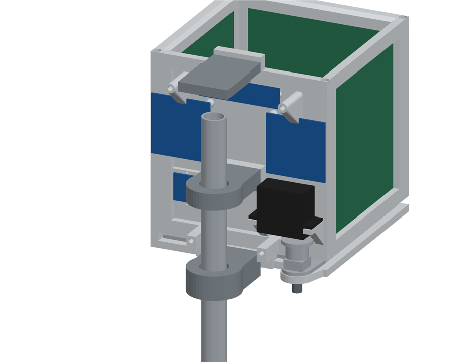
The main problem I saw here were wiring: too may wires going from the base to the chute.
Designing the mechanism
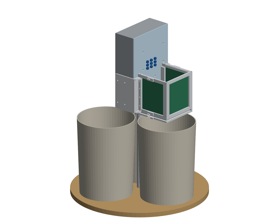
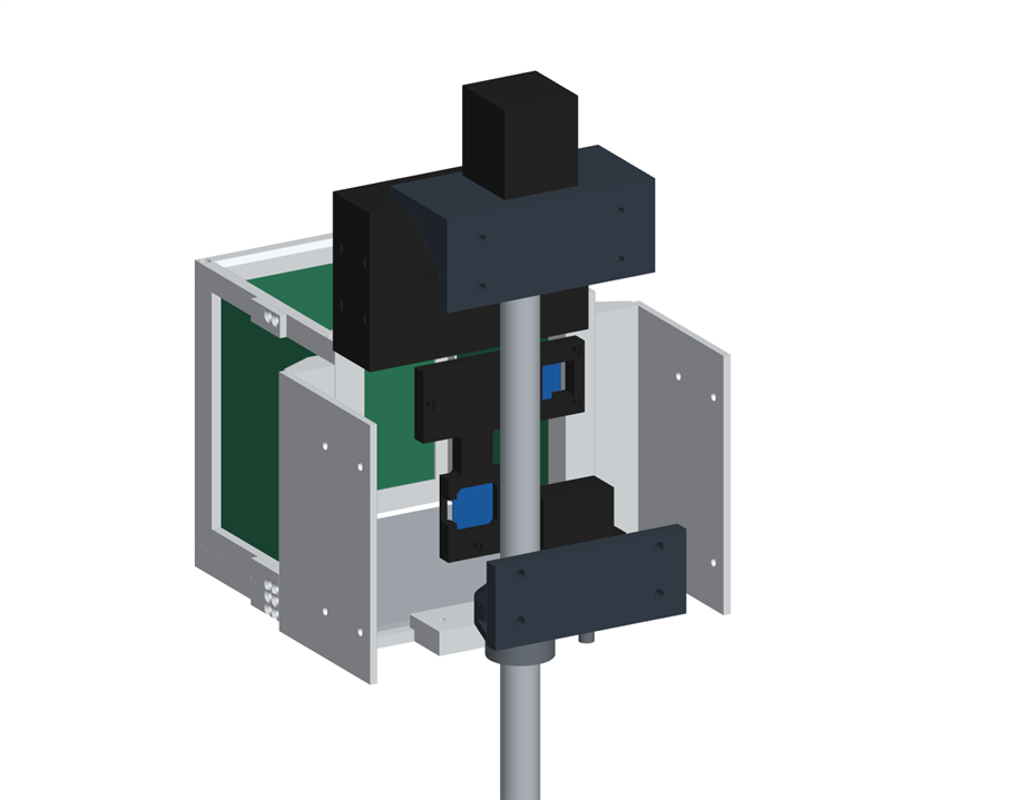
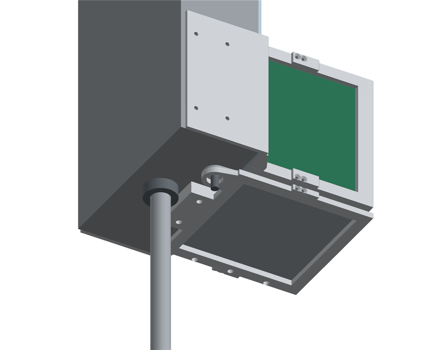
The solution was to make the Hammond box turn together with the chute. The box stands upright next to the chute, and its clear lid becomes the chute's back wall. The pole goes up inside the box, so the motor, the bearings and the electronics are all protected, and only power has to reach the turning part.
The pole and the bearings
The pole is an aluminium tube fixed to the base. The box turns around it on two printed mounts:, one on the floor of the box and one at the top.
The motor and the coupler
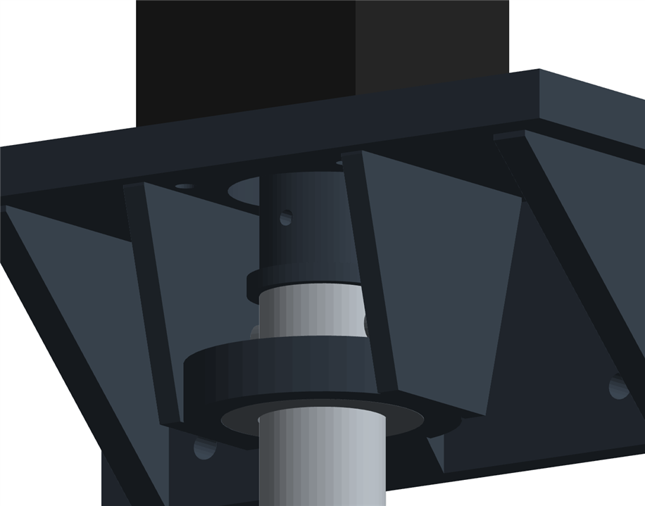
The whole assembly is moved by a NEMA 17 motor at the top, inside the box, with the shaft down. The motor is fixed to the box and its shaft is coupled to the pole, so when the motor turns, the box turns around the pole. A printed coupler goes into the bore of the pole. I used a TMC5272 drives, which I received for the "Start a movement" challenge
The chute frame
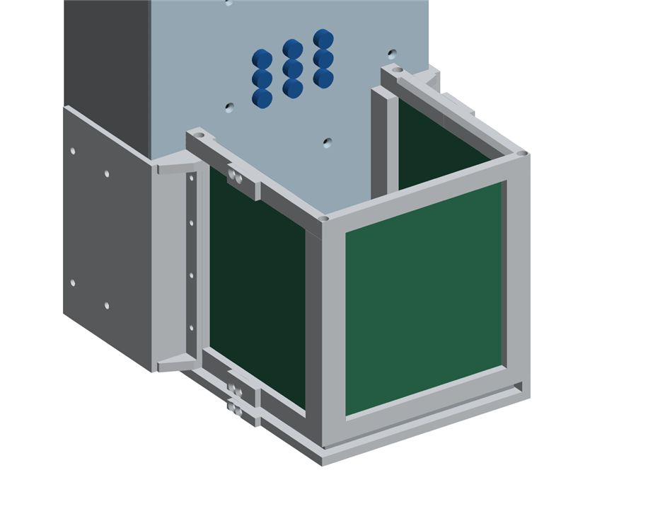
The chute is a U-shaped printed frame, open towards the box, with three 3 mm Coroplast panels that slide into grooves. Two printed brackets tie the frame to the side walls of the box, never to the lid, because the lid must come off for service.
The gate plate
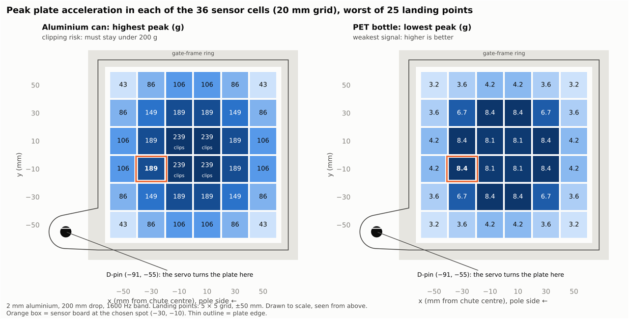
In post #2 I simulated plates of different materials and thicknesses. At the end I chose 2 mm aluminium: it shakes enough to give a clear signal also with a light PET bottle, and the ADXL372 can be placed in a spot where a can stays inside its ±200 g range. Glass will saturate it anyway, but there the microphone helps.
The gate servo
The plate is turned by a standard metal-gear servo inside the box. The plate swings 90° and leaves the opening completely free.
The sensors
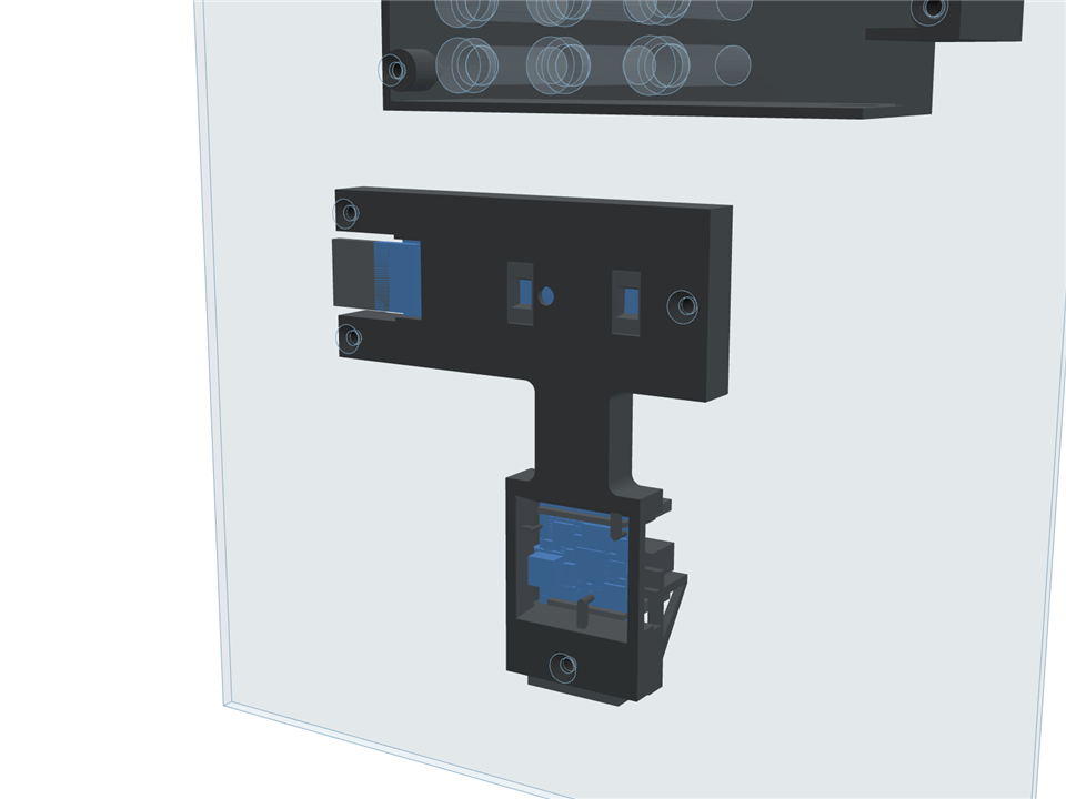
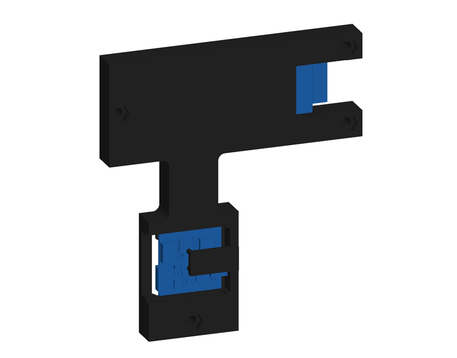
Since the clear lid is the back wall of the chute, the sensors can look into the chute through it. A printed case is screwed on the inside of the lid and holds the CN0569 and the Nicla Vision. The CN0569 is just abouve the Nicla, so it can detect the object as soon as it enters the chute. The walls of the case reach the lid so the IR LED cannot light the sensors through a reflection on the polycarbonate. Nicla board is down below, closer to the plate to listen to the sound the object makes.
The Nicla Vision board
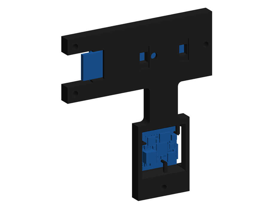
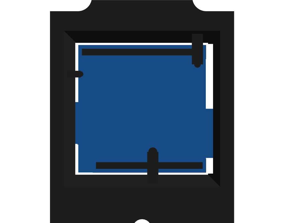
The Nicla Vision is a very interesting full-featured board, but I didn't consider how difficult it is to mount it properly, because it has no mounting holes at all, only the castellated pads, the connectors and the components on both sides. And I want the microphone exactly in front of a 4 mm hole in th elid. I explored some options for the case.
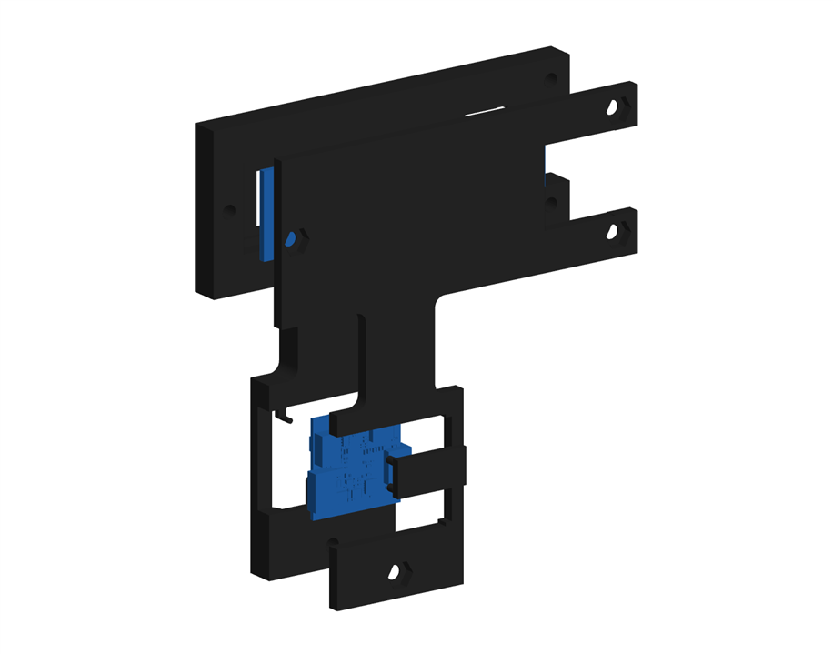
Option 1: a pocket clamped by the back cover. When the electronics moved behind the lid, I modelled the pocket directly from Arduino's STEP file, and the back cover of the sensor case clamps the board against the lid. This works for a bare board, but I soldered strip headers on mine, with the pins out of the back, and the cover was sitting exactly on the pins.
Option 2: pegs and stems. The current version holds the board by three small pegs on its top face, placed where there are no components, and two stems that come from the back cover and touch the back of the board, 0.2 mm off. Nothing touches the two pin rows, the USB and power connectors are free on one side, and there is a channel for the camera flex on the other side. It's not elegant, but it depends from nothing that the board doesn't have.
The LEDs
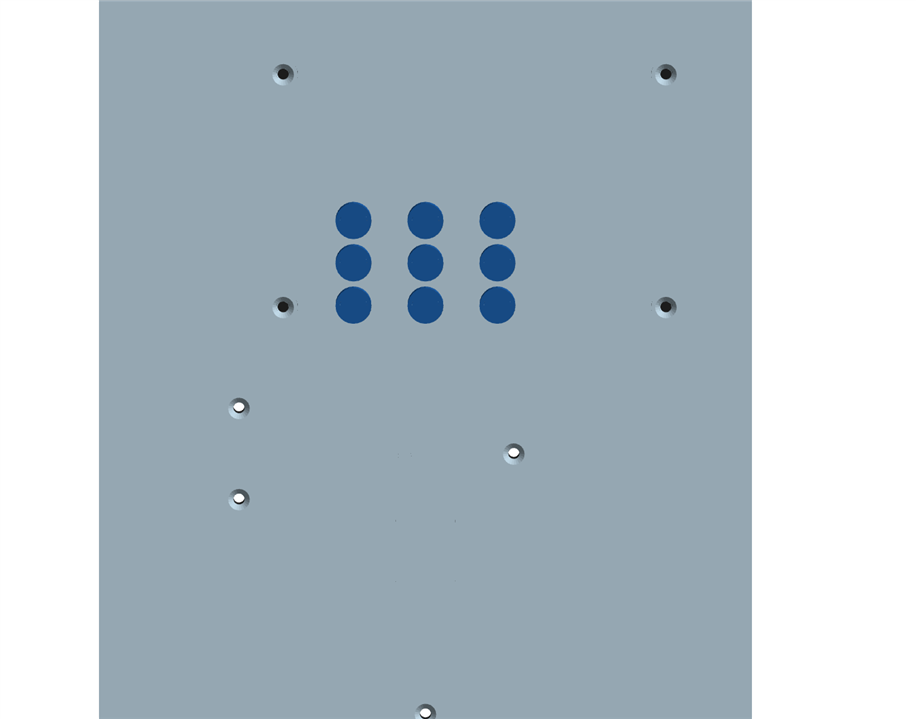
The nine CamdenBoss LEDs go directly through the lid, so the 3 mm lid is also their panel. A second printed case closes over them inside the box and carries the MCP23017 and the driver board. From the chute side, the user sees only the screws, the LEDs and the small holes.
Homing and position control
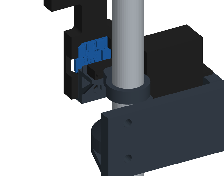
A stepper motor needs a home position. Since the box turns around a fixed pole, I put the cam on the pole and the microswitch on the box. The cam is a printed collar with one lobe and a grub screw: to set home, I loosen the screw, turn the cam until the lobe presses the lever with the chute in the home position, and tighten. After every sort the chute comes back home, and if the switch is not pressed there, the firmware knows that some steps were lost and makes the homing again.
What's next?
While my 3D printer is working hard to keep the pace with my ever-changing ideas, I am making the wiring to connect the Nicla board, the accelerometer and the IR sensor. This is the minimal configuration required to run some acquisition of microphone and accelerometer data
Thanks for reading, and stay tuned!