


As the first step of my project, I connected the TMC5272 eval kit to the Raspberry Pi. What I did is basically disconnect the board with the microcontroller and the USB port and solder some wires between the Raspberry Pi and the breakout board that originally used to connect the microcontroller board and the TMC5272 board.
Since I am using the SPI bus to communicate with the TMC5272, I wired these signals
- MOSI: Raspberry Pi Pin 19 (GPIO10) → TMC5272 SPI1_MOSI (Pin 32)
- MISO: Raspberry Pi Pin 21 (GPIO9) → TMC5272 SPI1_MISO (Pin 33)
- SCLK: Raspberry Pi Pin 23 (GPIO11) → TMC5272 SPI1_SCK (Pin 31)
- CS_0: Raspberry Pi Pin 24 (GPIO8) → TMC5272 SPI1_CSN (Pin 30)
- Power: Raspberry Pi Pin 2 (5V) → TMC5272 +5V_USB (Pin 5)
- Ground: Raspberry Pi Pin 6 (GND) → TMC5272 GND (Pin 3)
and this is the result

Next, I wrote a Python script to control the motor. This was a bit tricky, because the TMCL IDE does not provide an easy way to check which registers are written at startup, so it was a bit painful to go through the TMC5272 registers to find the right configuration to set. The script i mainly focused on the goal of my project, which is to drive the motor in velocity mode. I did not go in depth with all the other features of the component, but for sure it looks a very flexible piece of hardware which I can use in many future projects.
First of all, I opened the device /dev/spidev0.0, which is the SPI interface the TMC5272 is connected to
import spidev
import time

# SPI Setup
spi = spidev.SpiDev()
spi.open(0, 0)  # Open SPI bus 0, device 0 (adjust if using a different setup)
spi.max_speed_hz = 100000  # 100 kHz because of long wires. TMC5272 can handle up to 10 MHz
spi.mode = 0b00  # SPI mode 0 (TMC5272 default)
spi.bits_per_word = 8
Next, I created two function to read and write registers. TMC5272's SPI protocol is quite simple. The protocol handles only 32 bit values, and each request/reply is made up of 5 bytes. In case of a read request, you need to send
- the number of the register to read
- 4 dummy bytes just to generate the SPI clock and let the TMC5272 shift out the 32 bits of the register's values
TMC5272 replies with the following data
- 1 byte with status information, according to table below
- 4 bytes with the content of the register
Actually, I noticed that the 4 bytes returns the content of the registers requested in the last-but-one request. For this reason, in the script I send the read command twice
In case of a write request, you need to send
- the number of the register to read OR-ed with 0x80
- 4 bytes with the data to write
TMC5272 replies with the following data
- 1 byte with status information, according to table above
- 4 bytes with the content of the register
Here is the code I developed
READ_COMMAND = 0x00
WRITE_COMMAND = 0x80

# Function to send and receive data over SPI
def write_register(register, value):

    byte3 = (value >> 24) & 0xFF  # Most significant byte
    byte2 = (value >> 16) & 0xFF
    byte1 = (value >> 8) & 0xFF
    byte0 = value & 0xFF          # Least significant byte

    # Prepare the write command (0x80 | register_address for most TMC devices)
    command = WRITE_COMMAND | register
    # Send command (register address) and read the response (4 bytes for 32-bit data)
    response = spi.xfer2([command, byte3, byte2, byte1, byte0])

    # Response format: [status_byte, data_byte1, data_byte2, data_byte3, data_byte4]
    # Combine the data bytes into a single 32-bit value
    print(f"{response[0]:02X}")


# Function to send and receive data over SPI
def read_register(register):
    # Prepare the read command
    command = READ_COMMAND | register
    # Send command (register address) and read the response (4 bytes for 32-bit data)
    response = spi.xfer2([command, 0x00, 0x00, 0x00, 0x00])
    response = spi.xfer2([command, 0x00, 0x00, 0x00, 0x00])

    # Response format: [status_byte, data_byte1, data_byte2, data_byte3, data_byte4]
    # Combine the data bytes into a single 32-bit value
    status_value = (response[1] << 24) | (response[2] << 16) | (response[3] << 8) | response[4]

    print(f"0x{register:02X}: {response[0]:02X} {status_value:08X}")
    return status_value
With this two functions in place, I initialized the registers according to the datasheet
    print("Setting IHOLD_IRUN...")
    write_register(0x12, 0x04011F0A)
    print("Setting RAMPMODE...")
    write_register(0x07, 0x00000001)

    print("Setting CHOPCONF...")
    write_register(0x38, 0x10410153)

    print("Setting GCONF...")
    write_register(0x00, 0x00020002)

    print("Setting AMAX and DMAX...")
    write_register(0x20, 0x00000631)
    write_register(0x22, 0x00000631)
    print("Setting VMAX...")
    write_register(0x21, 0x00009B83)
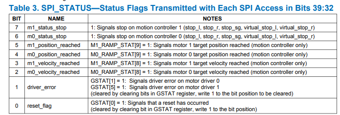
Let's go through each register with the help of some screenshot from TCML IDE application
- M0_IHOLD_IRUN: here I am setting the maximum run and standstill current. Run current is set to the maximum (0x1F, which means 32 out of 32 steps). In the future, I will try to find the optimal value for the motor run current, in order not to incur in overheating or overcurrent conditions
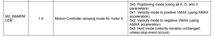
- RAMPMODE: I wrote the ramp mode to "velocity" for motor 0. As per the following table, you need to write 01b into the Least Significant bits of the register
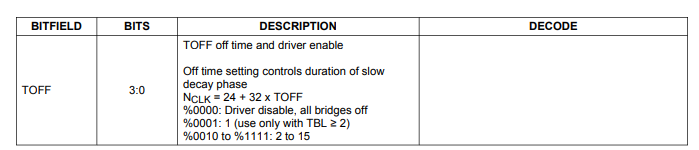
- M0_CHOPCONF: in this is a register, I only changed the 3 Least Signifcant bits because, according to the datasheet, driver is disabled by default I wrote b011 into the TOFF field. Bot sure this is the most appropriate value, but this is the value written also by TMLC IDE
- GCONF: this register has been set with the following configuration for both motors
- Driver enabled (bit 14)
- Use internal motion controller (instead of STEP/DIR signals) (bit 13)
- Use motor normal operation (the alternative is to control motor through serial interface) (bit 12)
- Disable Motor hard stop function, since ENC_A1 signal is not wired (bit 11)
- Disable DIAG information (bits 3 to 9)
- Default motor direction (bit 2)
- Enable step input filtering for StealthChop2 (bit 1)
- Disable the StealthChop2 mode (bit 0)
- AMAX and DMAX: this are the maximum acceleration and deceleration values. TMC5272 implements a quite complex ramp control algorithm, with several acceleration parameters. These parameters are shown in below diagram
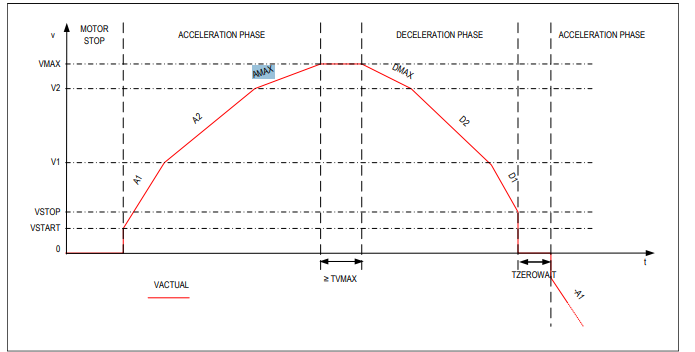
For the sake of simplicity, in this test I only configured AMAX and DMAX, and left the other parameters untouched. Accelerations are expressed in microsteps per unit of time squared. For the motor provided with the kit (which has a step angle of 1.8°), a microstep is equal to 1.8° / 256 ≈ 0.007° per microstep.
- VMAX: finally, I set the motor velocity (in microsteps per time unit). To stop the motor, I write 0 into the VMAX register