


Introduction
Let’s talk about the board Arduino UNO Q, the newest BOOM in the Single Board Computers (SBC). Despite the microprocessor and microcontroller are discrete elements in the board, it has a wide application field. The Qualcomm QRB2210 processor has a Quad-core ARM Cortex-A53 architecture with Linux integration by the implemented storage in the board. Some of the peripherals available consist of GPIOs, and serial communication. In addition to the processor, there are computer accelerators such as Adreno GPU and serial interfaces for cameras and display.
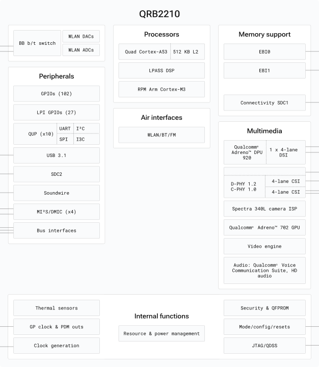
Figure 1. Processor architecture
On the other hand, the microcontroller platform consists of STM32U585 microcontroller. The microcontroller has an ARM Cortex-M33 with an ART accelerator. This platform is really interesting since it has ADCs up to 2.5 Msps with hardware over sampling and DACs with 12-bit resolutions. In addition to these elements, we are able to use integrated operational amplifiers with PGA.
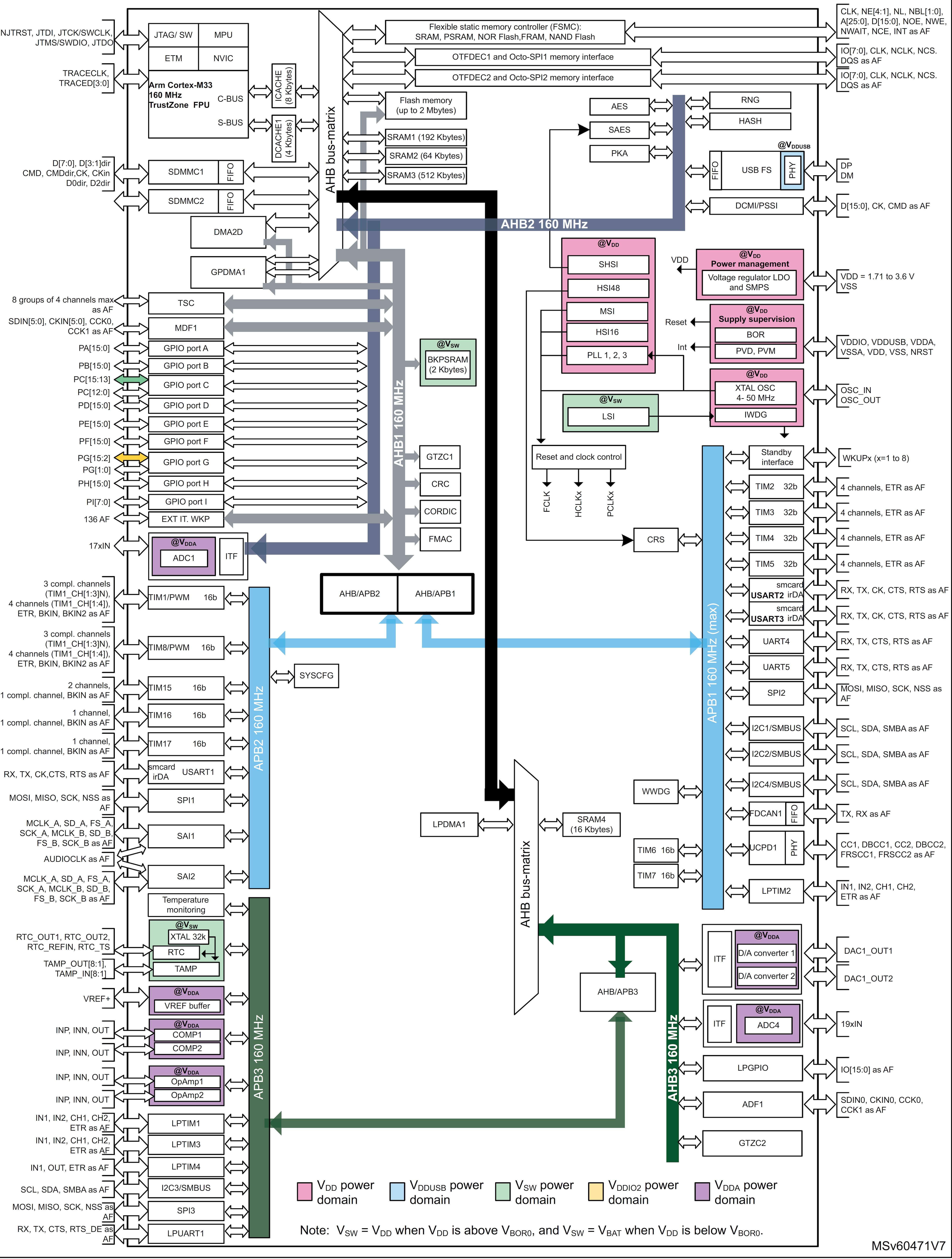
Figure 2. Microcontroller architecture
Methodology
Once the SBC is identified internally, one question raises up, how do the processors interact with external devices? Arduino provides documentation about which devices are connected in the processor, and which are connected to the microcontroller. According to the official documentation, all the legacy terminals have physical connection to the STM32U585 microcontroller
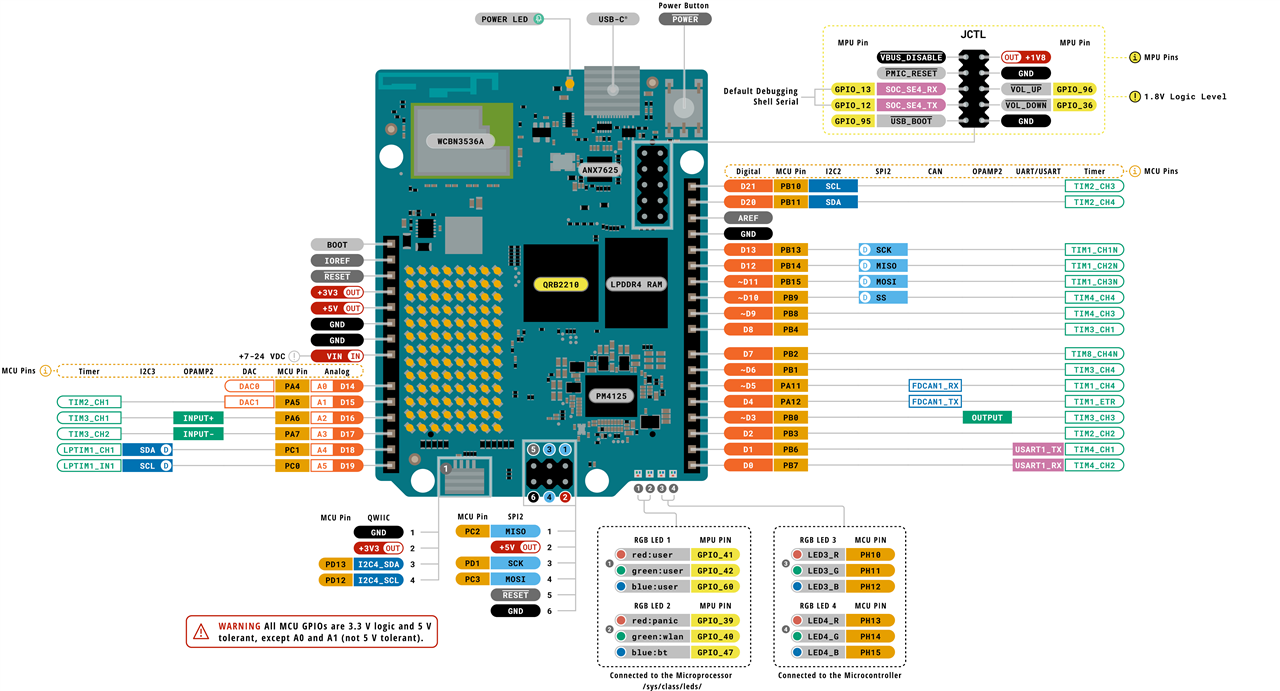
Figure 3. Arduino UNO Q pinout
The pinout shows that there is an opamp available to use in the system. This time, the microcontroller provides a Flexible Data CAN peripheral, only a transceiver is required for bus connection. The DACs are connected physically to the A0 and A1 channels, and so on. But, what about processor connections? There are three connections for the processor, the debugging port and two led ports. Some of the LEDs are related to network status and error status, but there is a LED for the user tests, and here is out objective this time.
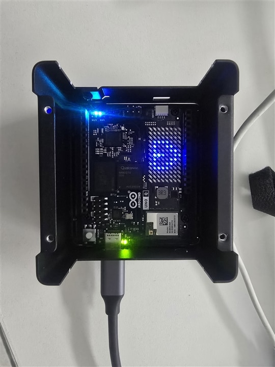
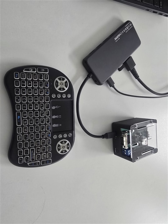
The blink example is usually used to test microcontroller operation, but this time we have an additional processing system, and it is required to observe if the operative system is able to modify status in the processor registers or interact with external interfaces. To do it I assembled a minimal system for usage with USB-C connection with a Hub or desktop terminal. A KKSB case is used to assembly part of the system and test if the default App has a correct operation. The first time you connect the system to the Hub you will see an Arduino logo animation followed by a heart logo animation if the Remote Procedure Call (RPC) layer has a valid connection between systems. Finally, at the end of the process I got the starter page to configure the SBC. You must consider a high precision power supply since the board could restart suddenly if the power supply does not meet the power features.
| {gallery}Start |
|---|
|
|
 |
 |
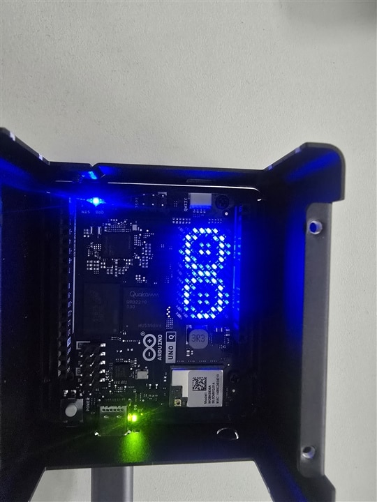
Figure 4 (a,b,c). Arduino UNO function sequence
It is possible turn on and turn off the user LEDs writing the command below in the terminal, as the official documentation suggests.
echo 1    | tee /sys/class/leds/unoq\:user-blue1/brightness   # set HIGH/ON
echo 0    | tee /sys/class/leds/unoq\:user-blue1/brightness   # set LOW/OFF
The documentation shows an older version of the brightness writing and additional code using python. But you are a great specialist in C, consequently, you decide use files in C language to operate the states.
First, create your workspace
cd ~/Documents/
mkdir C
cd C
mkdir Demo
cd Demo
touch makefile
touch demo.c
Editing the makefile simplifies the rules for the compilation and cleaning of the project. Using wildcards it is possible to configure our small project.
$(APP): $(APP).c
        gcc $^ -o $@

clean:
        rm *.o $(APP)
Secondly, the code implemented must be comprehensive to understand the data accesss and which value must be written.
#include<stdio.h>
#include<stdlib.h>
char *LEDS[] = {"/sys/class/leds/unoq:user-blue1/brightness",
                "/sys/class/leds/unoq:user-green1/brightness",
                "/sys/class/leds/unoq:user-red1/brightness"};
int main(int argN, char *argV[]){
        if(argN < 3){
                printf("Not enough arguments\n");
                return 1;
        }
        FILE *f = NULL;
        printf("%s\n", argV[1]);
        f = fopen(LEDS[atoi(argV[1])], "w");
        if(f == NULL){
                printf("error while user access to LED\n");
                return 1;
        }
        fwrite(argV[2], sizeof(char), 1, f);
        fclose(f);
        printf("Command executed\n");
        return 0;
}
The compilation and execution of the App is really simple, only the command made in the terminal will decode the rules to compile and verify the project dependencies. The App only requires two arguments: value N to connotate the LED and a V value to denotate the HIGH or LOW state. Both parameters, N, and V are not restricted integers.
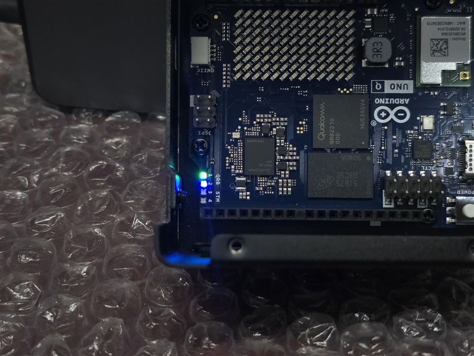
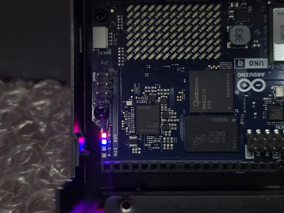
The results, for turn on the green LED it is required the command the execution of ./demo 1 1. Or the turn off of red LED is reached with ./demo 2 0
| {gallery}LEDs |
|---|
 |
 |
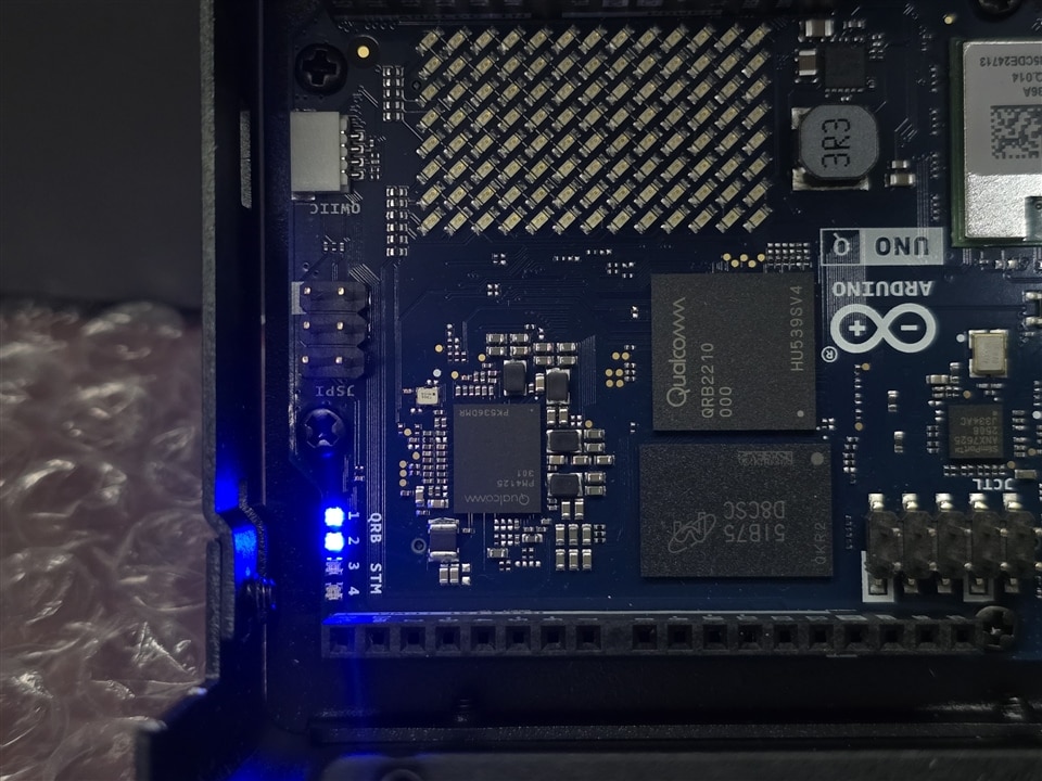 |
Figure 5 (a,b,c). Processor LED control test
The future
Let’s test the capabilities of the microcontroller, this is required since the data sharing and data interface is required by the processor, while the microcontroller acquires the signals and generates auxiliar signals for power electronics or other electromechanical conditioning. At this moment we have an Arduino UNO Q operative assembled on a KKSB case with the CAN board mounted and the LED access for future tests.
| {gallery}Final assembly |
|---|
 |
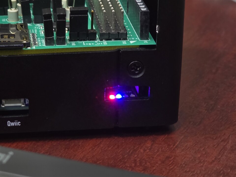 |
Figure 6 (a,b). Minimal assembly testing the LED brightness access

