


I spent a lot of time last month cleaning up my projects. I almost lost lost track of time. Now to convert the POC I made into a reliable data collection powerhouse, ArduinoQ running Zephyr on STM32 is new to me. Linux part i can handle.
Recap:
I’m developing a smart solar monitoring system that uses a clean reference panel to eliminate weather effects and directly quantify dust-induced losses in real time. With edge AI and environmental sensing, the goal is to predict the right moment to cleanbefore efficiency drops enough to matter.
Setting Up Arduino Q
I downloaded AppLab quickly from the official website, connected the Arduino Q via a USB-C and blasted away through the configuration screen. In this regard, it was easy, although the update took time.

And it is always an Ritual that i need to blink an LED whenever i get a new hardware and so I used the example. I have to admit it, Using Zephyr , An Python Code and RPC connection between them just to blink LED is like using cannon to Kill a mosquito.

Internet Research to Answer the Question
After Looking at some Internet on how to get CAN to work, I came to a conclusion that ArduinoQ cannot run the CAN Controller on the STM32
- https://forum.arduino.cc/t/arduino-uno-q-canfd-controller-use/1414493
- https://forum.arduino.cc/t/uno-q-can-library/1416035
- https://forum.arduino.cc/t/trying-to-get-fdcan-working-on-the-uno-q/1431867
And so the challenge begins. If i cannot easily interface the CAN Peripheral on STM32 then my next idea became to have an additional board like Teensy 3.2 or my Nucleo F303Re which as a CAN Peripheral as a bridge between ArduinoQ and the MAX33041E. Then the number of bridges made me uneasy. Imagine Q's Qualcomm Chip -> Q's STM32 Chip -> Nucleo F303RE -> MAX33041E -> CAN Bus. It was ridiculous. I looked if i can break the Qualcomm's Bridge and somehow run the STM32 using STM32HAL. I came to know that the Linux installation contains OpenOCD and Zephyr's Documentation that the Physical connection between MPU and MCU is LPUART managed by an arduino-router service on the linux

Taking Control of the STM32 from the hands of Qualcomm Chip
Step 1: Disable arduino-router Service
I connected to the ArduinoQ's terminal via SSH ssh arduino@<boardname>.local where boardname is the name you gave it while setup. The Password is again the same as you gave in the setup
sudo cp /etc/systemd/system/arduino-router.service \
        /home/arduino/arduino-router.service.bak
sudo rm /etc/systemd/system/arduino-router.service
sudo systemctl mask arduino-router
sudo systemctl daemon-reload
sudo pkill -9 -f arduino-router
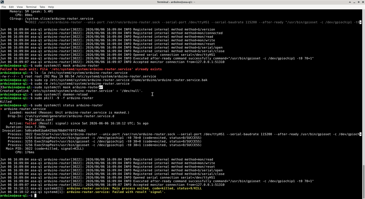
I ensured that i restarted the Q to ensure that the service does not pop up back again.
Step 2: Setting up the STM32MX Project
From the Schematics of Arduino Q here: https://docs.arduino.cc/resources/schematics/ABX00162-schematics.pdf , I got the full chip code - STM32U585AII6TR, set up the project on STM32MX with the clock and just LPUART, LED, CAN

 \
\
The clock values as as below
RCC_OscInitStruct.OscillatorType = RCC_OSCILLATORTYPE_HSE;
RCC_OscInitStruct.HSEState       = RCC_HSE_ON;
RCC_OscInitStruct.PLL.PLLState   = RCC_PLL_ON;
RCC_OscInitStruct.PLL.PLLSource  = RCC_PLLSOURCE_HSE;
RCC_OscInitStruct.PLL.PLLM       = 1;
RCC_OscInitStruct.PLL.PLLN       = 10;
RCC_OscInitStruct.PLL.PLLR       = 1;   // 16 * 10 / 1 = 160 MHz
I generated the code, starting with a simple blink. btw, Flash latency must be FLASH_LATENCY_4 at VOS1 / 160 MHz — anything lower causes a hard fault on the first cache miss.
Step 3: The Blinking Ritual
The onboard LED is on PH10, active-HIGH
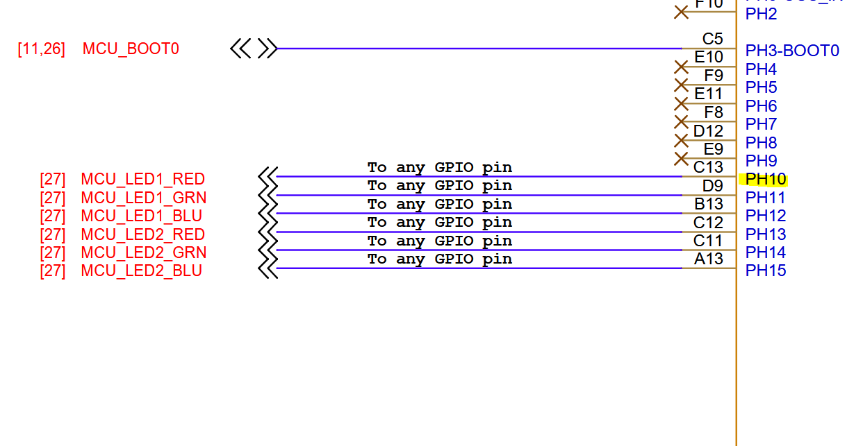
/* MX_GPIO_Init USER CODE section */
__HAL_RCC_GPIOH_CLK_ENABLE();

GPIO_InitTypeDef GPIO_InitStruct = {0};
GPIO_InitStruct.Pin   = GPIO_PIN_10;
GPIO_InitStruct.Mode  = GPIO_MODE_OUTPUT_PP;
GPIO_InitStruct.Pull  = GPIO_NOPULL;
GPIO_InitStruct.Speed = GPIO_SPEED_FREQ_LOW;
HAL_GPIO_Init(GPIOH, &GPIO_InitStruct);

/* Main loop */
HAL_GPIO_TogglePin(GPIOH, GPIO_PIN_10);
HAL_Delay(500);
Step 4: Setting up the LPUART1
/* USER CODE BEGIN Includes */
#include <stdio.h>
/* USER CODE END Includes */

/* USER CODE BEGIN 2 */
char tx_buf[64];
/* USER CODE END 2 */

/* Main loop */
int len = snprintf(tx_buf, sizeof(tx_buf), "hello from STM32\r\n");
HAL_UART_Transmit(&hlpuart1, (uint8_t *)tx_buf, len, 100);
#!/usr/bin/env python3
import serial, sys

ser = serial.Serial('/dev/ttyHS1', 209700, timeout=5)
print(f"Listening on /dev/ttyHS1 at 209700 baud...")
try:
    while True:
        line = ser.readline()
        if line:
            print(line.decode('utf-8', errors='replace').strip())
except KeyboardInterrupt:
    ser.close()
Step 5: Now ArduinoQ CAN
The STM32 has CAN pins on PA11 (RX) / PA12 (TX). Before connecting to a real bus, verify the peripheral and transceiver with an external loopback test. External loopback drives the TX pin through the transceiver while simultaneously receiving
the frame internally. The STM32 provides its own ACK, so it keeps transmitting even with no termination resistor or other node on the bus. And Ensure that the Jumpers are all in default positions as https://www.analog.com/media/en/technical-documentation/data-sheets/MAX33041ESHLD.pdf except for JU11, you need to switch it to the 3.3V side so that it can receive the power from Arduino Q's 3.3V

FDCAN_FilterTypeDef sFilterConfig;
sFilterConfig.IdType       = FDCAN_STANDARD_ID;
sFilterConfig.FilterIndex  = 0;
sFilterConfig.FilterType   = FDCAN_FILTER_MASK;
sFilterConfig.FilterConfig = FDCAN_FILTER_TO_RXFIFO0;
sFilterConfig.FilterID1    = 0x000;
sFilterConfig.FilterID2    = 0x000;  // mask=0 → accept all standard frames
HAL_FDCAN_ConfigFilter(&hfdcan1, &sFilterConfig);
HAL_FDCAN_Start(&hfdcan1);
// User Loop
FDCAN_TxHeaderTypeDef txHeader;
uint8_t canTxData[8] = {0xDE, 0xAD, 0xBE, 0xEF, 0x01, 0x02, 0x03, 0x04};
txHeader.Identifier         = 0x123;
txHeader.IdType             = FDCAN_STANDARD_ID;
txHeader.TxFrameType        = FDCAN_DATA_FRAME;
txHeader.DataLength         = FDCAN_DLC_BYTES_8;
txHeader.ErrorStateIndicator = FDCAN_ESI_ACTIVE;
txHeader.BitRateSwitch      = FDCAN_BRS_OFF;
txHeader.FDFormat            = FDCAN_CLASSIC_CAN;
txHeader.TxEventFifoControl = FDCAN_NO_TX_EVENTS;
txHeader.MessageMarker      = 0;

HAL_StatusTypeDef tx_status =
    HAL_FDCAN_AddMessageToTxFifoQ(&hfdcan1, &txHeader, canTxData);
HAL_Delay(10);

FDCAN_RxHeaderTypeDef rxHeader;
uint8_t canRxData[8];
int len;

if (tx_status != HAL_OK) {
    len = snprintf(tx_buf, sizeof(tx_buf), "CAN TX ERR %d\r\n", (int)tx_status);
} else if (HAL_FDCAN_GetRxFifoFillLevel(&hfdcan1, FDCAN_RX_FIFO0) > 0) {
    HAL_FDCAN_GetRxMessage(&hfdcan1, FDCAN_RX_FIFO0, &rxHeader, canRxData);
    len = snprintf(tx_buf, sizeof(tx_buf), "CAN OK id=0x%03lX d=%02X%02X%02X%02X\r\n",
                   (unsigned long)rxHeader.Identifier,
                   canRxData[0], canRxData[1], canRxData[2], canRxData[3]);
} else {
    len = snprintf(tx_buf, sizeof(tx_buf), "CAN FAIL no rx\r\n");
}
HAL_UART_Transmit(&hlpuart1, (uint8_t *)tx_buf, len, 100);
and we get the CAN OK id=0x123 d=DEADBEEF on the serial output. And on the Oscilloscope I get the beautiful differential signal.

Finally we made the ArduinoQ CAN.
Final Notes
Arduino Q looking at the specs seems promising but there are lot of usability issues with the software and they should have given an easy connection to STM32 for power users. None the less, I managed to overcome the limitation Zephyr OS gave - Ability to use the CAN peripheral on the STM32 and in that process, i unleashed full potential of the STM32. Next will be to actually connect an Receiver side to the CAN Bus and establish and transfer some poetry.


