


A computer system is not able to process an analog signal. Despite this fact, a digital system, such as a processor, can process an enormous amount of data to make decisions about physical variables. How is a physical phenomenon described by the data stored in a memory section? The answer is simple but quite difficult to implement. An analog-to-digital converter is required to take an analog signal and convert it to digital data. This process involves a time-based sampling to observe the phenomenon, quantify the observed value and assign a digital code that is representative for the digital system.
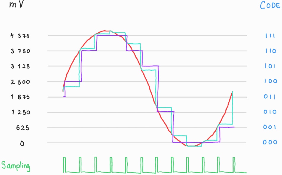
Figure 1 Analog-to-Digital convertion representation
One of the most important components in signal processing, whether analog or digital, is the signal conditioner. A signal conditioner is part of the sensing system since it converts a phenomenon into a voltage response. There are many types of temperature transducers that detect changes in the environment such as RTDs and NTCs. This time, thanks to the On the Line Design Challenge, there are K-type thermocouples. In my last blog I wrote about the probe mounting for harsh environments and fluid isolation. However, a question arose: How can I connect the probe to store data in the processor memory when the sensing stage provides some mV/°C and the dynamic range of the ADCs is huge compared with the thermocouple response? An example considered is for a 1V1 ADC_REF (silicon gap) for a 10-bit resolution ADC. In this case, the minimum detectable value is around 1.07 mV, but the ADC_REF must be small to detect small changes in temperature. This is not feasible for the measurement system using the default references on the board for each channel required.
Methodology
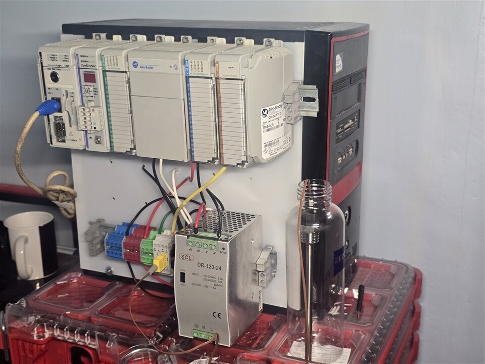
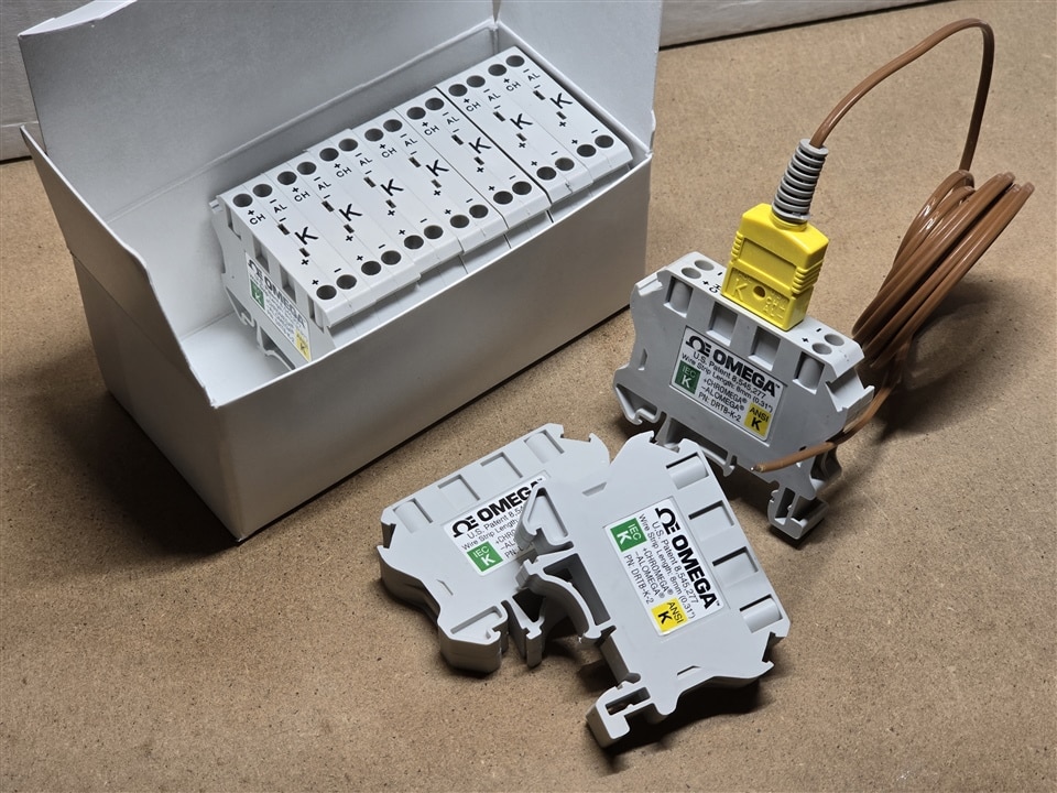
After exploring multiple options for creating an interface between the thermocouple and the data storage, I decided to use a commercial option to acquire temperature data. The first option I considered was using the DeviceNet protocol with an Allen Bradley PLC. Although the 1769-32E CPU is not recommended for new designs, it can perform interesting tasks. At least four thermocouples can be connected using the 1769 Thermocouple module, but the connection of Cold Junction Compensation (CJC) is required for the correct measurement of the environment. On the other hand, special thermoblocks and wire extensions are required for the connection with the module since a small wiring variation can induce offset and/or non-linearities in the measurement. Another option is to use temperature transmitters or analog front ends (AFE). While these elements have the same inconvenience of the thermocouple module for wiring, most of the AFE found has a temperature range above 0 °C. For test purposes are useful, but in the future the system requires measurement below this magnitude. The last option is the UT325F of UNI-T thermometer system. This equipment has up to 4 channels in multiple kinds of probes; it is possible to adjust the temperature offset since the CJC is internal and it has a Windows/Android application to capture data.
| {gallery}Interfaces |
|---|
 |
 |
|
|
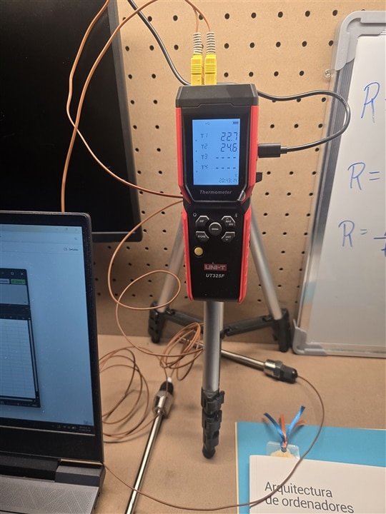
Figure 2 Data acquisition assembly options for thermocouple connection
As you wonder, I asked myself a question, is it possible to get data in the Arduino UNO Q Linux system? The answer, YES!!!
I did a lot of tests capturing the data and recognizing patterns in the received frame. The procedure consisted of the connecting and disconnecting the probes in each channel of the thermometer. I recognized some number patterns heating the probe with my hand, but I was not able to understand it at all. Aided by an AI tool I recognized two important patterns the data is transmitted in little endian while the CRC is transmitted in big endian. The data is repetitive, but I am not sure why at the moment to write this blog. And the third pattern recognized completely by me is to inform if a probe is connected to a specific channel. This task was in a PC since the equipment has a CH340 USB-to-UART variant which Arduino UNO Q Linux image has not a driver to handle communication. This was solved compiling and installing a driver available here: https://learn.sparkfun.com/tutorials/how-to-install-ch340-drivers/linux
And the results were incredible

Figure 3 Project transfer from the Arduino UNO Q to the PC by ssh copy

Figure 4 Serial port frame capture with data decoding
import serial
import struct
import time
from datetime import datetime

SERIAL_PORT = '/dev/ttyCH341USB0'
BAUD_RATE = 115200
TIMEOUT = 1
FRAME_LEN = 56

def compute_checksum(data):
	"""Calculate big-endian 16-bit checksum"""
	total = sum(data) & 0xFFFF					# 16-bits CRC
	return total.to_bytes(2, 'big')

def parse_temperature(frame):
	"""
	Extract 4 Float numbers in little endian format
	Initial index is equal to 5
	"""
	start = 5
	floats = []
	for i in range(4):
		b = frame[start + i*4 : start + i*4 + 4]
		if len(b) == 4:
			val = struct.unpack('<f', b)[0]
			floats.append(val)
		else:
			floats.append(None)
	return floats

def parse_connected(frame):
	"""
	Verify that a Thermocouple N has a connected sensor
	Each bytes illustrates that the channel has a connected thermocouple if
	the code is 0x00, or 0x30 if not
	"""
	start = 21
	channels = []
	for i in range(4):
		v = frame[21 + i]
		if v == 0x00:
			channels.append(True)
		else:
			channels.append(False)
	return channels

def read_and_validate(ser):
    """Serial port data reading. If the received frame is valid then return it"""
    buffer = bytearray()
    while True:
        byte = ser.read(1)
        if not byte:
            continue
        buffer.append(byte[0])

        if len(buffer) >= 2 and buffer[-2] == 0xAA and buffer[-1] == 0x55:
            while len(buffer) < FRAME_LEN:
                b = ser.read(1)
                if not b:
                    break
                buffer.append(b[0])
            if len(buffer) >= FRAME_LEN:
                frame = buffer[-FRAME_LEN:]
                data_part = frame[:-2]
                recv_checksum = frame[-2:]
                calc_checksum = compute_checksum(data_part)
                if recv_checksum == calc_checksum:
                    return frame
                else:
                    print("Wrong checksum")
                    buffer.pop(0)
            else:
                buffer.clear()
        else:
            if len(buffer) > FRAME_LEN * 2:
                buffer = buffer[-FRAME_LEN:]


def main():
	try:
		ser = serial.Serial(SERIAL_PORT, BAUD_RATE, timeout=TIMEOUT)
		dFile = open("data.csv", "w")
		dFile.write("t,T1,T2,T3,T4\n")
		while True:
			ser.reset_input_buffer()
			frame = read_and_validate(ser)
			if frame:
				print("Received Frame [hex]:", ' '.join(f'{b:02x}' for b in frame))
				print("╔═════════════════════════╗")
				temps = parse_temperature(frame)
				valid = parse_connected(frame)
				dFile.write(f"{datetime.now().strftime('%Y-%m-%d %H:%M:%S')},")
				for i in range(0, len(temps)):
					if(valid[i] == True):
						print(f"║ Temperature {i + 1}: {temps[i]: 5.1f} °C ║")
						dFile.write(f"{temps[i]},")
					else:
						print(f"║ Temperature {i + 1}:  NaN  °C ║")
						dFile.write(f"NaN,")
				print("╚═════════════════════════╝", end="\033[F\033[F\033[F\033[F\033[F\033[F")
				dFile.write("\b\n");
				time.sleep(1)
	except serial.SerialException as e:
		print(f"Serial por error: {e}")
	except KeyboardInterrupt:
		print("\nExecution stopped by the user")
	finally:
		if 'ser' in locals() and ser.is_open:
			ser.close()
		if 'dFile' in locals() and not dFile.closed:
			dFile.close()

if __name__ == "__main__":
	main()
The future
Now, it is time to integrate the RCP interface for the usage of the microcontroller to activate the compressor. Actually, the implemented script can receive data, process and write a CSV file to be stored in memory for future consult and analysis, but it is not able still to make decisions. The last test will consist of data sharing between the processor and microcontroller to test the system threshold and hysteresis for a full-operation test.
| {gallery}achievements |
|---|
|
|
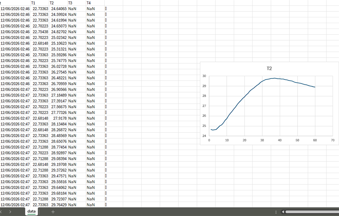 |
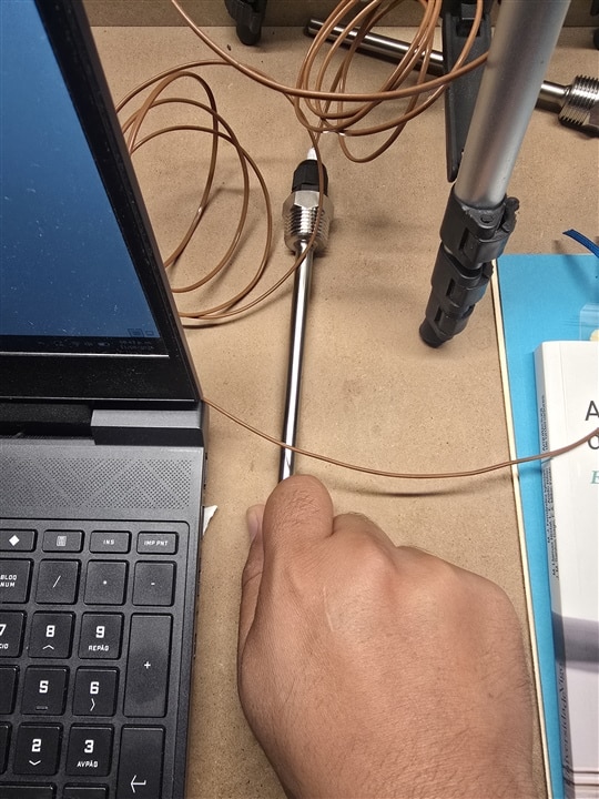
Figure 5 Actual temperature data storing achievement
