


At this stage I have gone through all the material in the Software course. It does not feel complete though as labs 9 and 11 require some additional hardware which I don’t have yet. I will not cover these two labs in this blog since I am still hoping to include more material on them in the later posts.
From the remaining labs, the most important concept I learnt is how to create a complete boot image for the device on an SD card that includes:
- Bootloader;
- Power Management Unit;
- Main Application;
- FPGA bitstream.
This is the fundamental knowledge you need to have to deploy a software application on the Ultra96. Labs 4, 5 and 6 prepare the components listed above and then it all comes together in Lab 7.
SW Lab 4
Objectives:
- Add new software applications to SDK
- Use example code to target the UART in a Hello World application
- Apply example project templates, including
- Memory Tests
- Peripheral Tests
- Identify application code size and location
- Modify linker scripts to change the target memory location
Lab 4 sums up the theoretical foundations covered in the first three labs and asks to create your first project. This is a very common Hello World program that uses one of the board’s UART ports to display a message in the terminal. Next, two example projects, Peripherals Tests and Memory Tests, are explored. What is more interesting is that memory mapping for the application is discussed in more detail. Basically, there are three memory regions available on Zynq MPSoC:
- Block RAM (BRAM) in Programmable Logic – 16KB;
- LPDDR4 – 2GB;
- On Chip Memory (OCP) – 256KB.
It is demonstrated that there is a very convenient graphical interface to modify the Linker script. This interface can be accessed through the project explorer by right-clicking on the project header and selecting “Generate Linker Script”. You can then select in which of the memories listed above to place the Code section, Data section and Heap and Stack. You also still have an option to explore the source of the script and make any necessary edits manually.
The SDK is by default configured to rebuild the project every time a change is made to the configurations, which is very handy for the small projects when the build process does not take long. This applies to the generation of a new linker script, too.
SW Lab 5
Objectives:
- Set up the hardware for operation
- Program a bitstream to the PL
- Configure the ARM PS over JTAG using TCL
- Run an application
- Debug an application
In Lab 5 we finally get to connect the hardware and test the applications from the previous lab. I had no issues during the hardware setup process, the serial drivers for the JTAG module were detected straight away and I was able to link the device to my VM. I was quite surprised everything worked from the first attempt as serial drivers tend to be a pain. This assumes that all the steps during the VM setup were completed carefully.
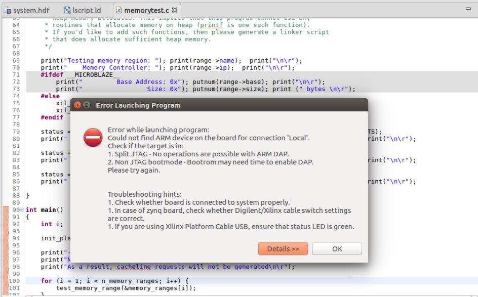
Figure 1: Connection Error
However, I had some issues with loading the Hello World application to the board with error message shown in Figure 1. The possible issues listed there were not applicable in my case – so I just relaunched the run. The error message did not appear anymore, and FPGA programming was initiated as expected.
Xilinx SDK debugger seems to be very powerful and offers quite a few extra features compared to the traditional GDB Debugger:
- Homogenous and heterogeneous multi-processor support;
- Linux application debug on the target;
- Hierarchical Profiling;
- Bare-metal and Linux development;
- Supporting both SMP and AMP designs;
- Associate hardware and software breakpoints per core;
- NEON library support.
The SDK also inherits all the benefits of the Eclipse platform. You get a separate debugging view which simplifies the process and makes all the necessary information visible. Setting the breakpoints, stepping through the code – everything just works as you would expect.
SW Lab 6
Objectives:
- How to generate the FSBL
- What the FSBL application includes
- How to recognize some of the initialization sequences
Next we explore the initialisation of the board by creating two new projects: one for the First Stage Bootloader (FSBL) and one for the Power Management Unit (PMU).
FSBL is responsible for starting up the Processing Unit and this can be divided into 4 stages:
- Initialise the bootloader;
- Prepare boot device (JTAG or SD card);
- Load the partitions from boot media (in case of SD);
- Handoff to application.
The purpose of the PMU is to handle the power management, system errors and executing software test library.
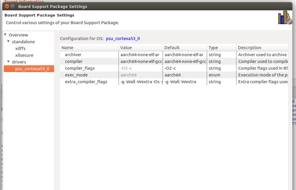
Figure 2: Setting Compiler Optimisation Level for BSP
Another important point covered in the lab is where to set the compiler options for the project. Note that it needs to be done separately for the application and the BSP. It is done via project properties for the application code and in “Manage BSP Settings” menu for the BSP.
SW Lab 7
Objectives:
- How to create a boot image
- Boot from SD Card
Once the previous labs are completed, it is finally time to put all the components together and create a boot image for Ultra96. This is done by selecting the application project and choosing the corresponding option as in the screen shot below.
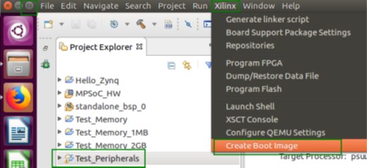
Figure 3: Creating a Boot Image
Now it’s time to add the files for the bootloader, PMU, FPGA bitstream and application file. The order in which they are loaded is very important and should be as follows:
- FSBL;
- PMU;
- FPGA bitstream;
- Application .elf file.
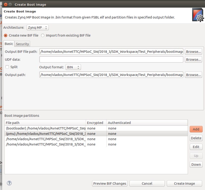
Figure 4: BIF file and Binary Generation
This way two output files are generated: BOOT.bin image file and a .bif file (Boot Image Format) which lists the partitions and the corresponding attributes.
I then moved the .bin file to the SD card and changed the boot mode switches on the Ultra96. It powered up correctly, however, the peripherals test got stuck halfway through. A similar issue was described in one of the other blogs and it also provides some guidance how to solve it: P2P: SW Lab 7 Road Block
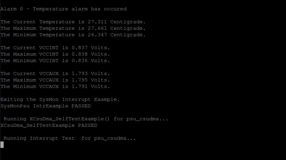
Figure 5: Peripherals Test Stuck
SW Lab 8
Objectives:
- Create a complete project archive
- Create a new, duplicate project by importing your archive
- Create a new application, and import the sources for that application
This was a quite straightforward exercise of exporting and importing the whole project. I did not have any issues with the lab instructions. However, the number of steps required to export the full project is overwhelming and the process is not obvious without the instructions. Below are the 5 main things that need to be done to successfully export your project:
- Export project source files as an archive (.zip or other);
- Export Debug and Run configurations;
- Export breakpoints;
- Export your local repository settings (remote repositories info + project preferences + linker script generation settings);
- Create another archive that includes all components above.
Most of these operations are handled form the SDK menu. However, Step 4 is not automated at all and you have to move all the files yourself.
To sum up, it is great that the SDK attempts to help you with the export at many stages but overall the process is not the most user-friendly due to the manual file moving operations that need to be done outside of the SDK, which might cause errors.
SW Lab 10
Objectives:
- How to enable one of the Xilinx libraries within your standalone BSP
- How to leverage one of the Xilinx libraries from a standalone application
- How to configure and use the Xilinx System Monitor.
Finally, I learnt how to add Xilinx libraries to the BSP using the FAT File System library as an example. It allows to you to read and write from/to an SD card which is very handy for data logging for instance. It is great that this was included in the course as I am sure many will use the option to store some files externally and work with them during the application run-time in the final projects.
Adding a library is as simple as ticking a box in the BSP settings. You can perform all the necessary configurations for the library in the same window.
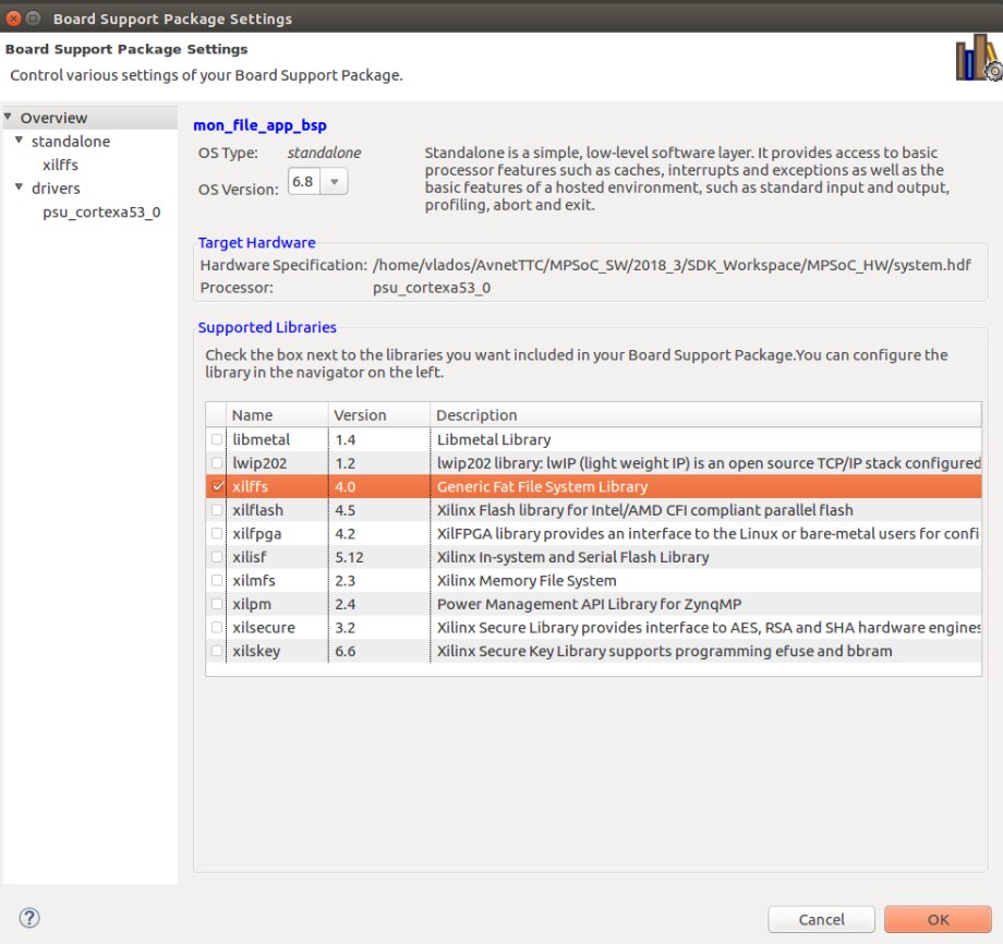
Figure 6: Adding Xilinx Libraries to BSP
We used the readings of the internal temperature sensor and an ADC to test the capabilities of the xilffs library. I did not have any issues with running the application and the temperature readings were displayed in the terminal as well. However, I noticed that the fan on the board is working non-stop and Ultra96 gets quite hot – even though the application is not really “heavy”, the temperature reached 63 degrees C. Some components on the board like the USB ports were heated quite badly as well.
I am wondering if anyone else is experiencing the same?
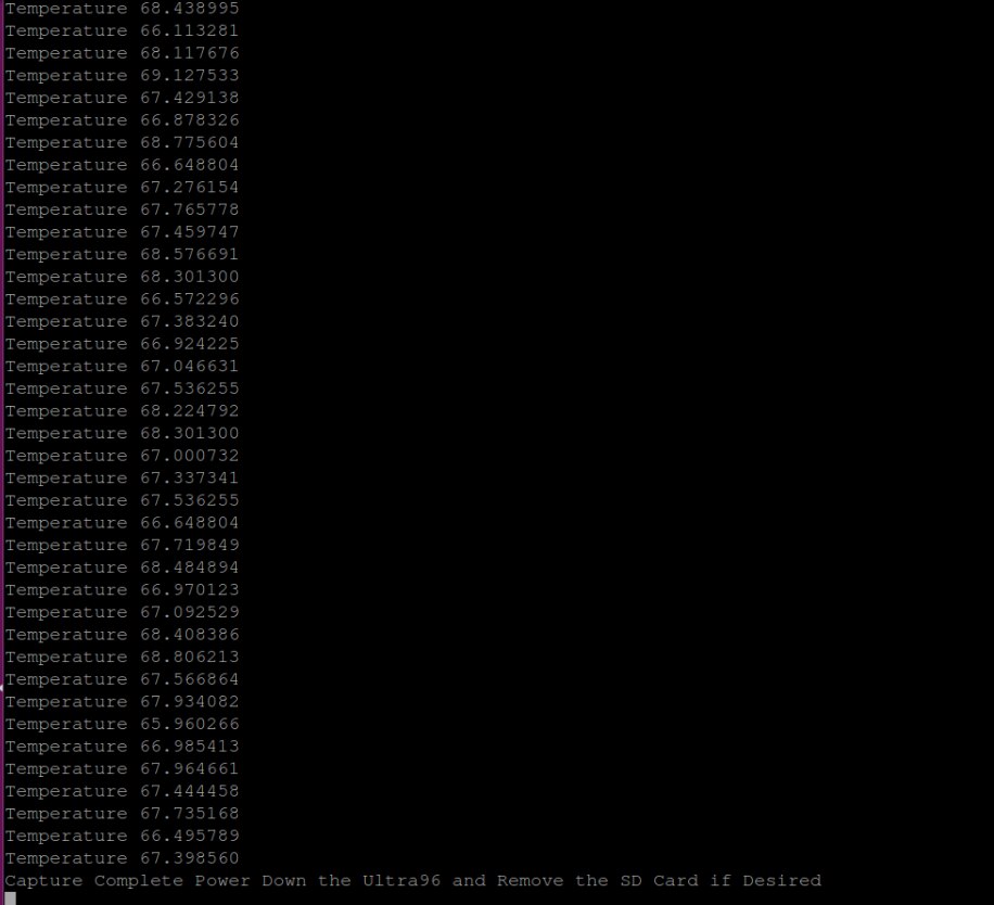
Figure 7: Temperature Readings
This concludes the Software module for now but, as I said, I am planning to revisit the two remaining labs if get the hardware required.
Next is the Hardware module!
Top Comments
-

cmelement14
-
Cancel
-
Vote Up
0
Vote Down
-
-
Sign in to reply
-
More
-
Cancel
Comment-

cmelement14
-
Cancel
-
Vote Up
0
Vote Down
-
-
Sign in to reply
-
More
-
Cancel
Children