


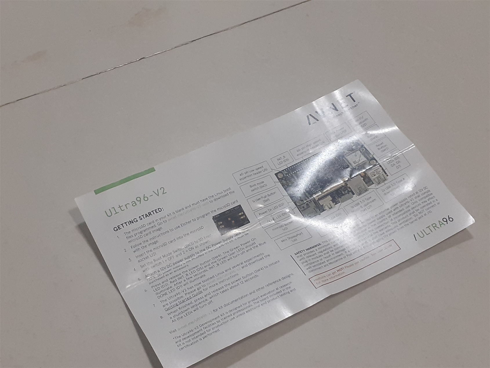
Introduction of Ultra 96 v2 kit
The Ultra 96 v2 is Arm-based, Xilinx Zynq UltraScale+ MPSoC development board based on the Linaro 96 Boards Consumer Edition Specification. The kit contains certified radio module from Microchip. All components of the kit are updated to allow industrial temperature grade options. Additional power control and monitoring will be possible with the included Infineon Pmics. the Ultra96-V2 boots from the provided Delkin 16 GB microSD card. Engineers have options of connecting to Ultra96-V2 through a Webserver using integrated wireless access point capability or to use the provided PetaLinux desktop environment which can be viewed on the integrated Mini DisplayPort video output. Multiple application examples and on-board development options are provided as examples are also provided.
Ultra96-V2 provides four user-controllable LEDs. Engineers may also interact with the board through the 96Boards-compatible low-speed and high-speed expansion connectors by adding peripheral accessories such as those included in the MikroE Click Mezzanine for 96Boards (available as an accessory).
Micron LPDDR4 memory provides 2 GB of RAM in a 512M x 32 configuration. Wireless options include 802.11b/g/n Wi-Fi and Bluetooth 5 Low Energy. The radio module is Agency Certified in over 75 countries. UARTs are accessible on a header as well as through the expansion connector. JTAG is available through a header. The convenient JTAG/UART Pod (available as an accessory) provides both JTAG and UART connections via USB. I2C is available through the expansion connector.
Two Microchip USB3320 USB 2.0 ULPI Transceivers and one Microchip USB5744 4-Port SS/HS USB Controller Hub enable multiple USB connections. Ultra96-V2 provides one upstream (device) and two downstream (host) USB 3.0 connections. A USB 2.0 downstream (host) interface is provided via the high speed expansion.
The integrated power supply generates all on-board voltages from an external 12V supply (available as an accessory).
Features of the kit
- Xilinx Zynq UltraScale+ MPSoC ZU3EG A484
- Micron 2 GB (512M x32) LPDDR4 Memory
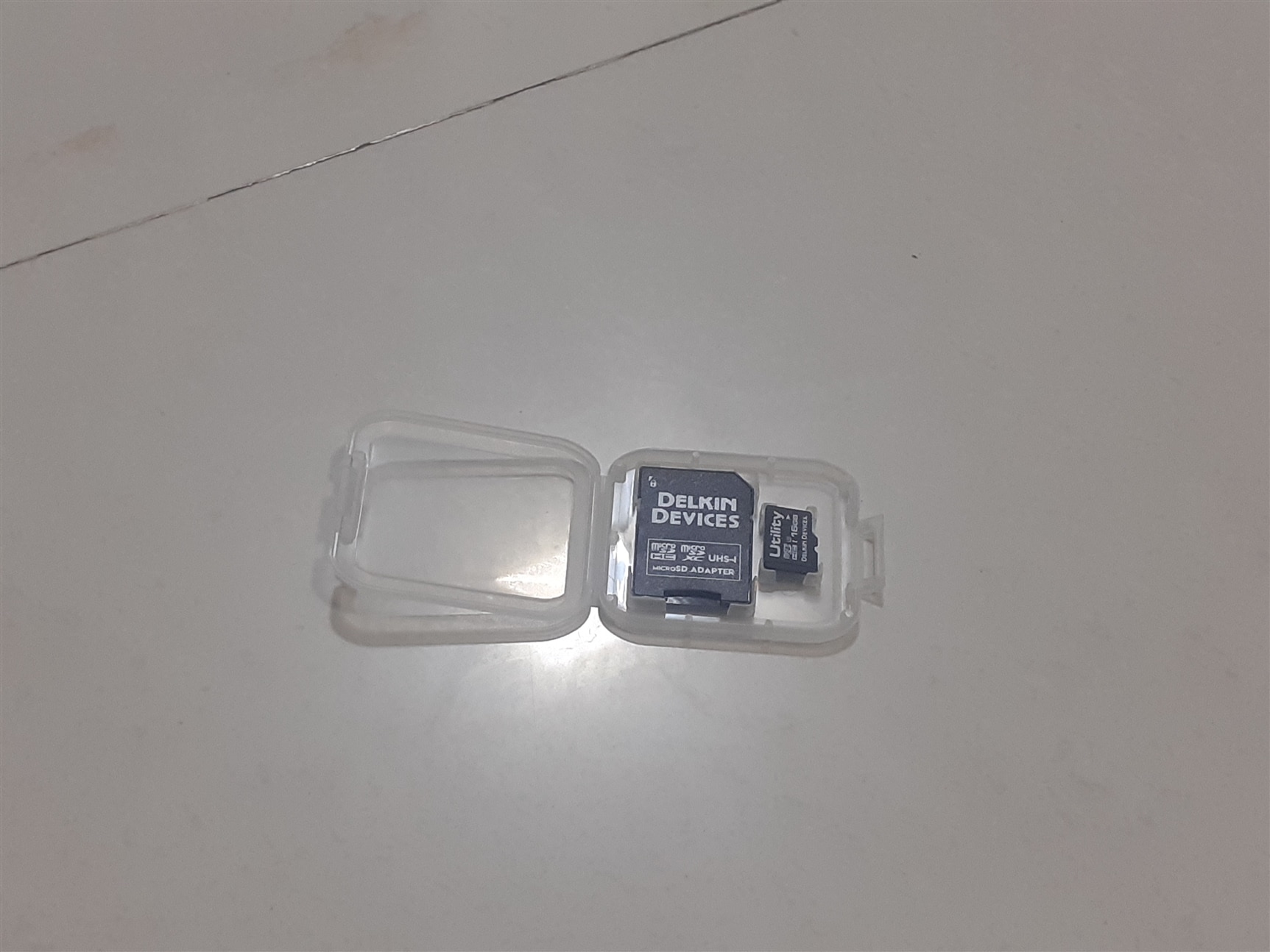
- Delkin 16 GB microSD card + adapter
- PetaLinux environment available for download
- Microchip Wi-Fi / Bluetooth
- Mini DisplayPort (MiniDP or mDP)
- 1x USB 3.0 Type Micro-B upstream port
- 2x USB 3.0, 1x USB 2.0 Type A downstream ports
- 40-pin 96Boards Low-speed expansion header
- 60-pin 96Boards High-speed expansion header
- 85mm x 54mm form factor
- Linaro 96Boards Consumer Edition compatible
Various application for which the Ultra96-v2 kit can be used
- Artificial Intelligence
- Machine Learning
- IoT/Cloud connectivity for add-on sensors
- Embedded Computing
- Robotics
- Entry level Zynq UltraScale+ MPSoC development environment
- Training, prototyping and proof-of-concept demo platform
- Wireless design and demonstrations using Wi-Fi and Bluetooth
What does the kit contains
AES-ACC-U96-4APWR Power Supply
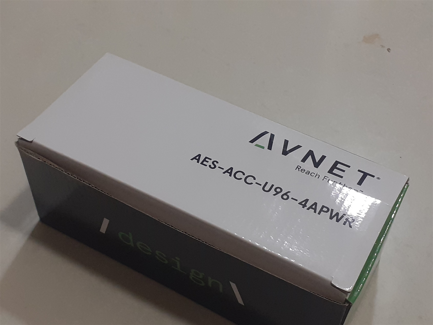
Things included in the power supply Box:-
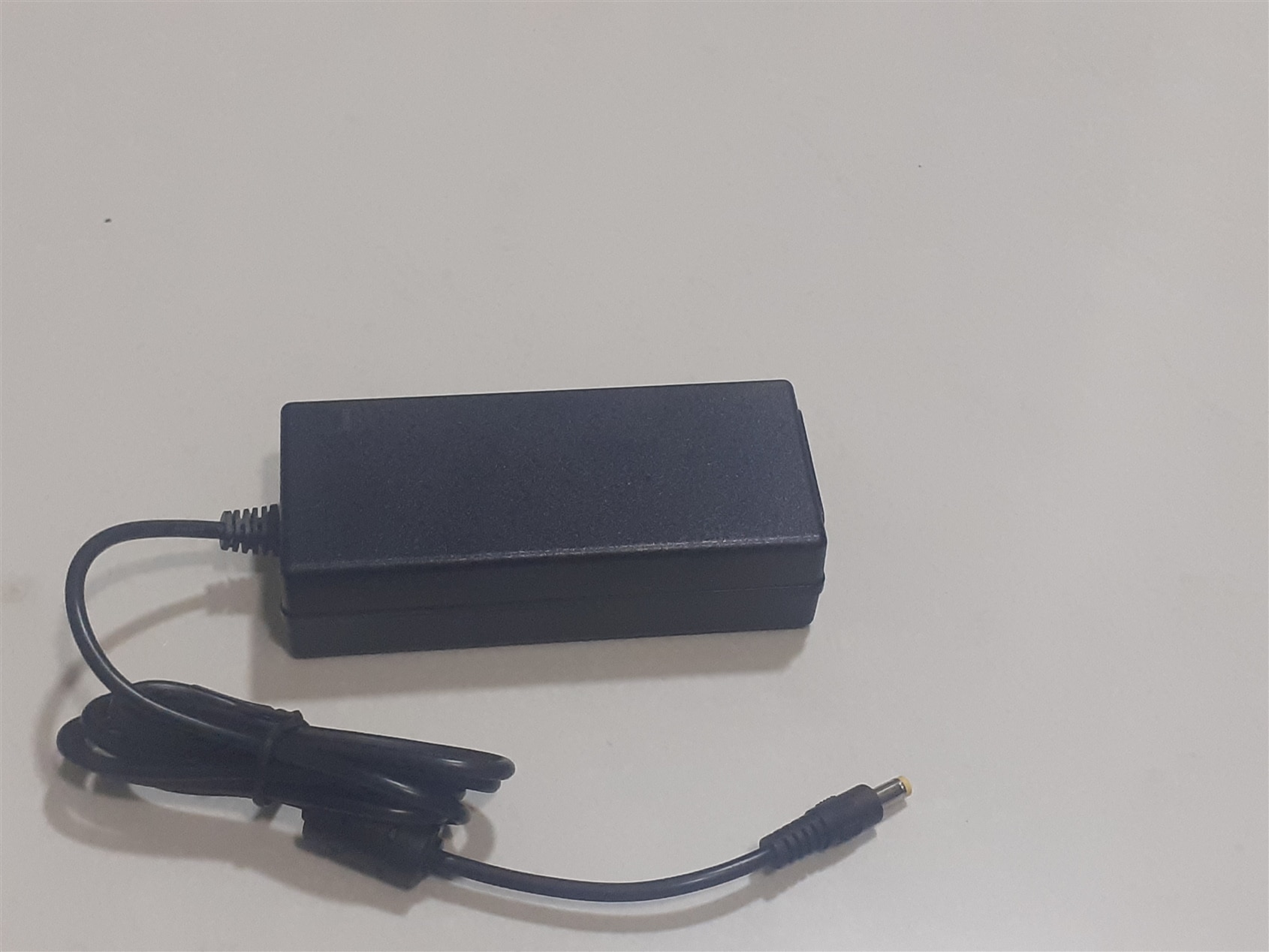
12 volt 4 amp power brick (input:- 100-240 volt, current 1.5amp)
Two pin European style electrical connector
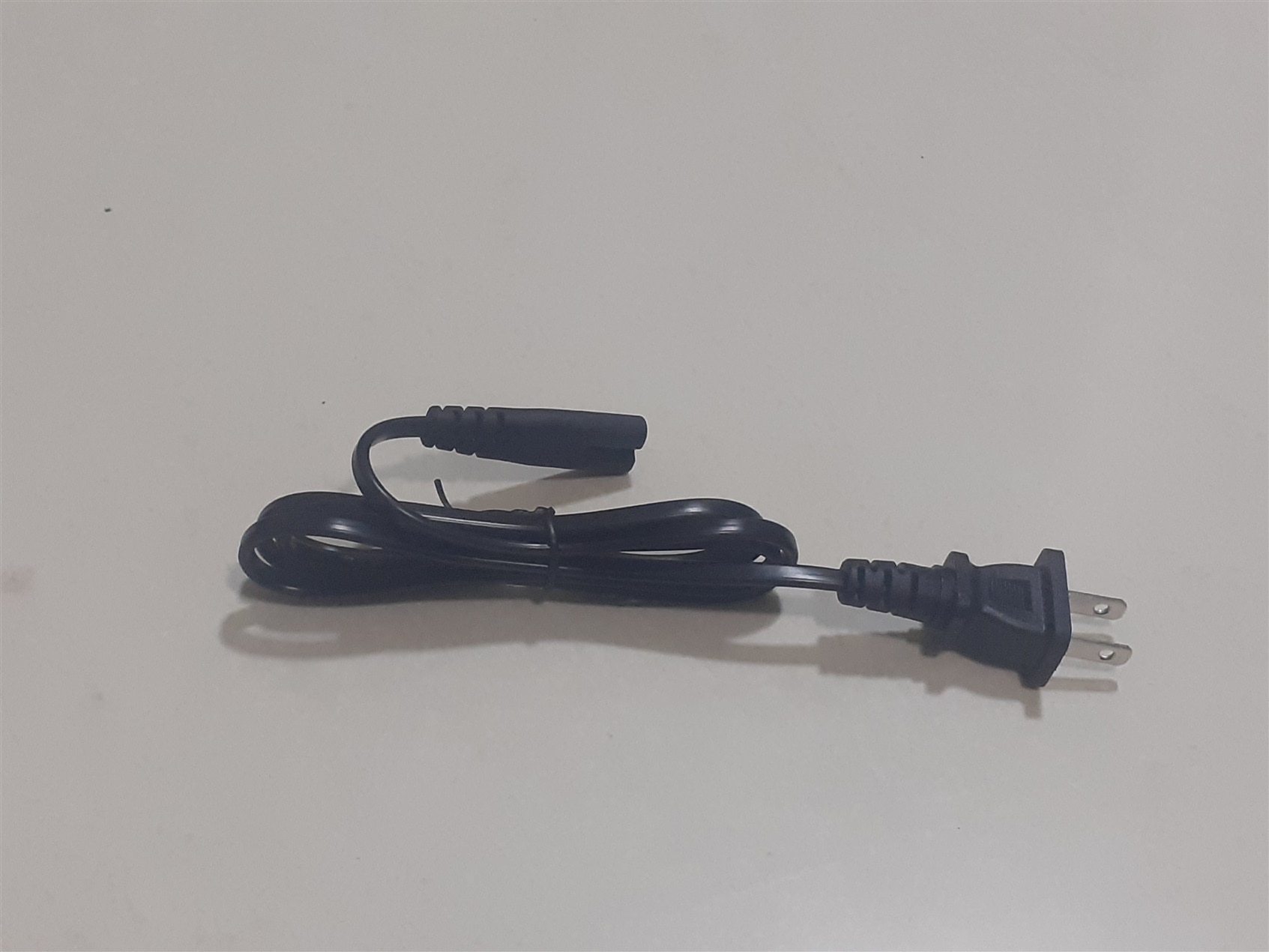
3 pin European style socket connector without fuse
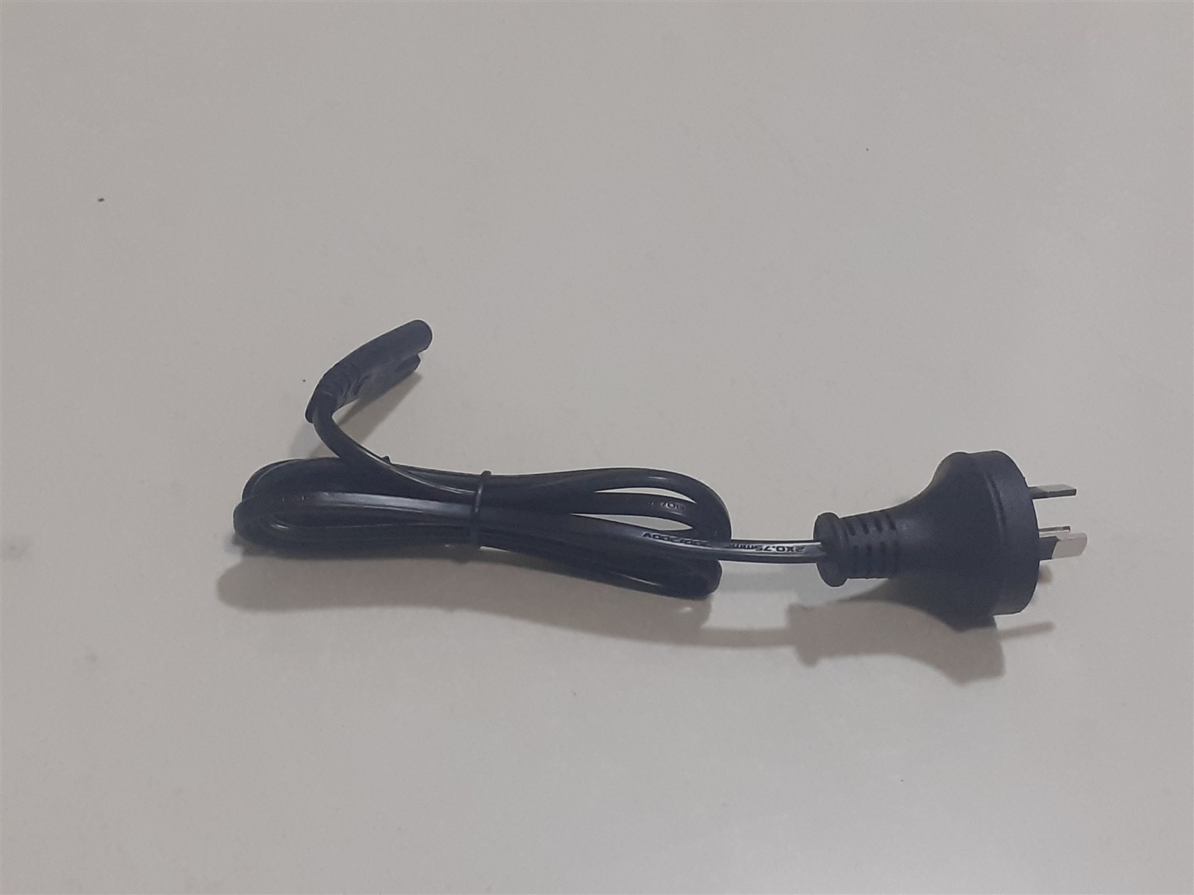
3 pin European style connector with fuse
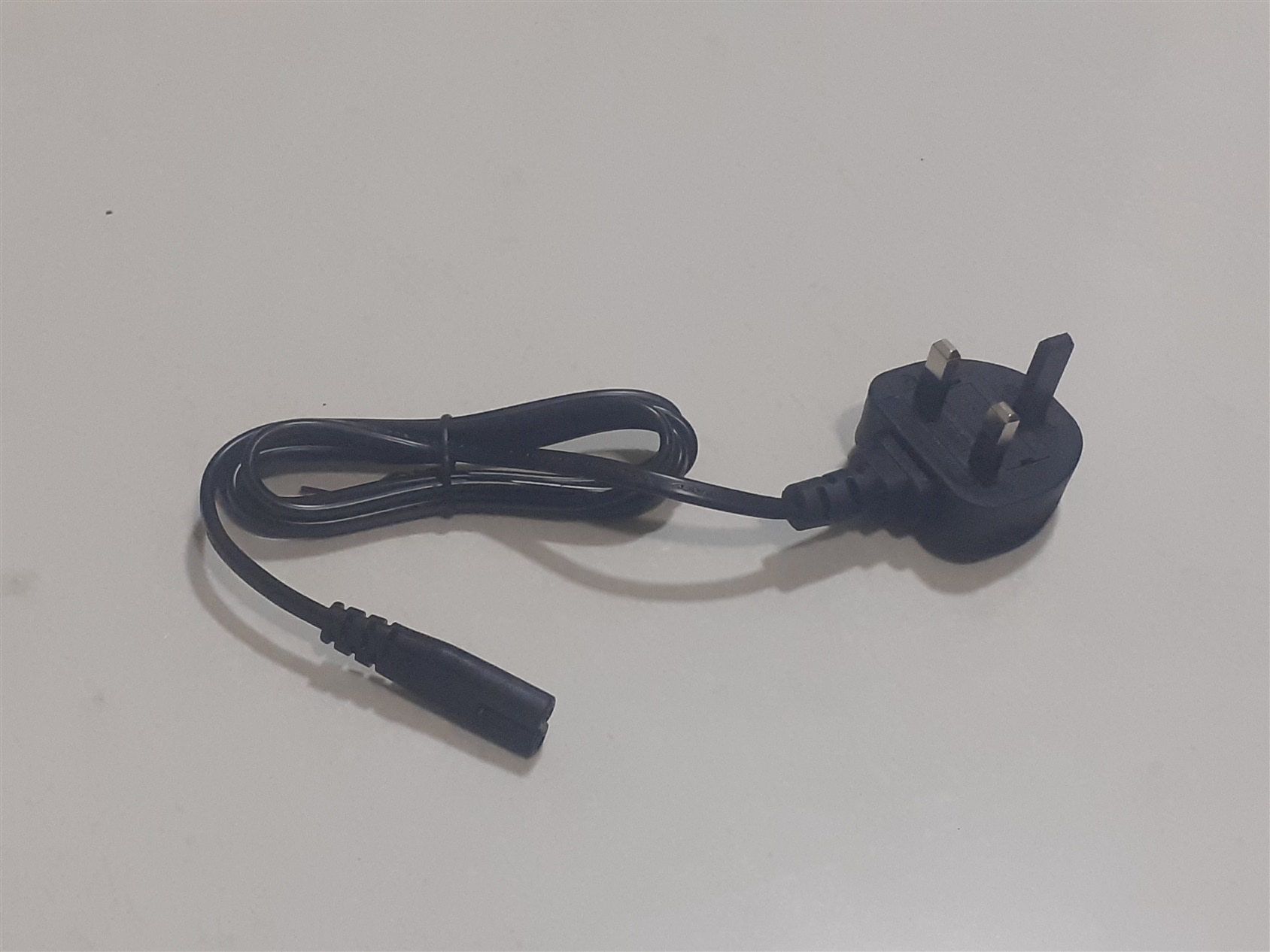
2 pin Indian connector

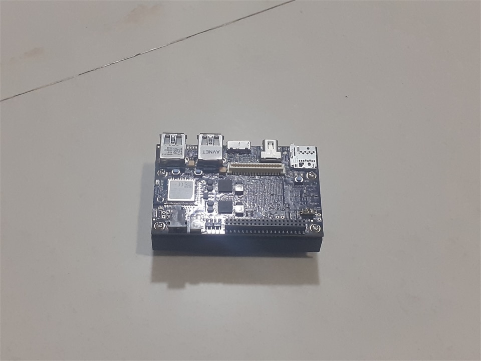
Ultra96-V2 box
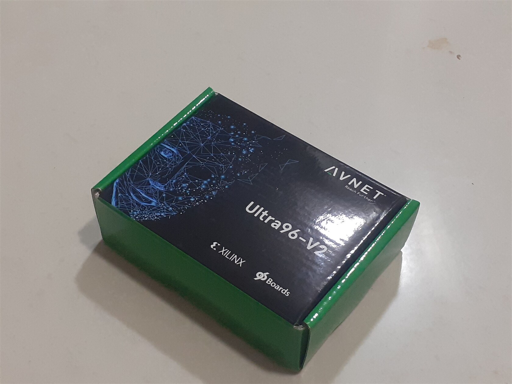
Things included in the Ultra96-V2 box Box:-
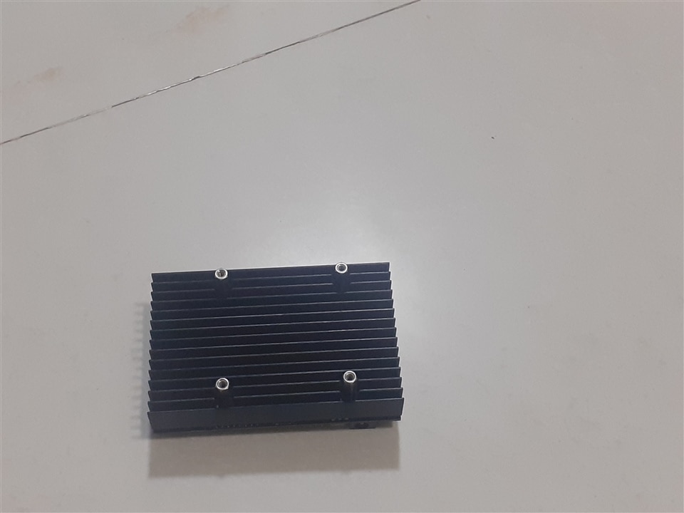
AES-ULTRA96-V2-I-G development board heatsink without fan
Operating manual
16GB sd card for storing petalinux
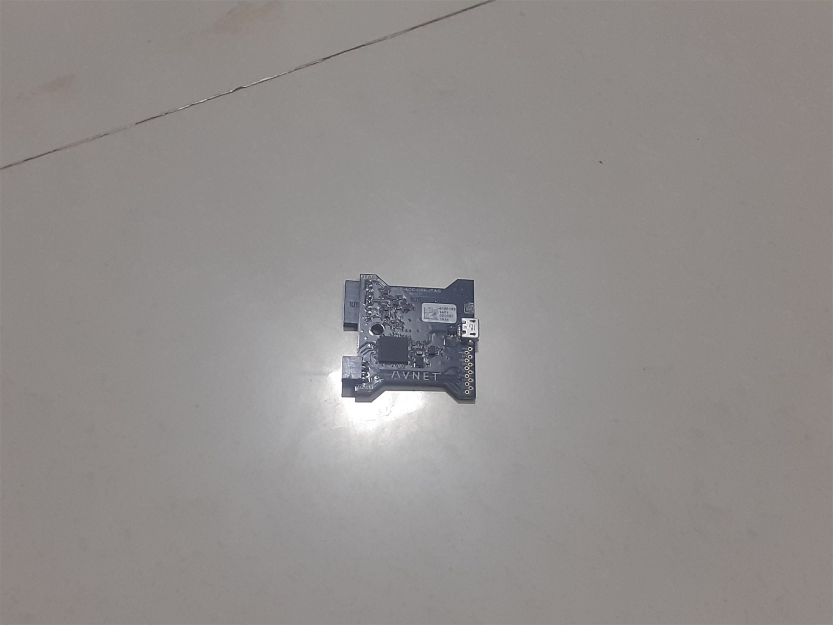
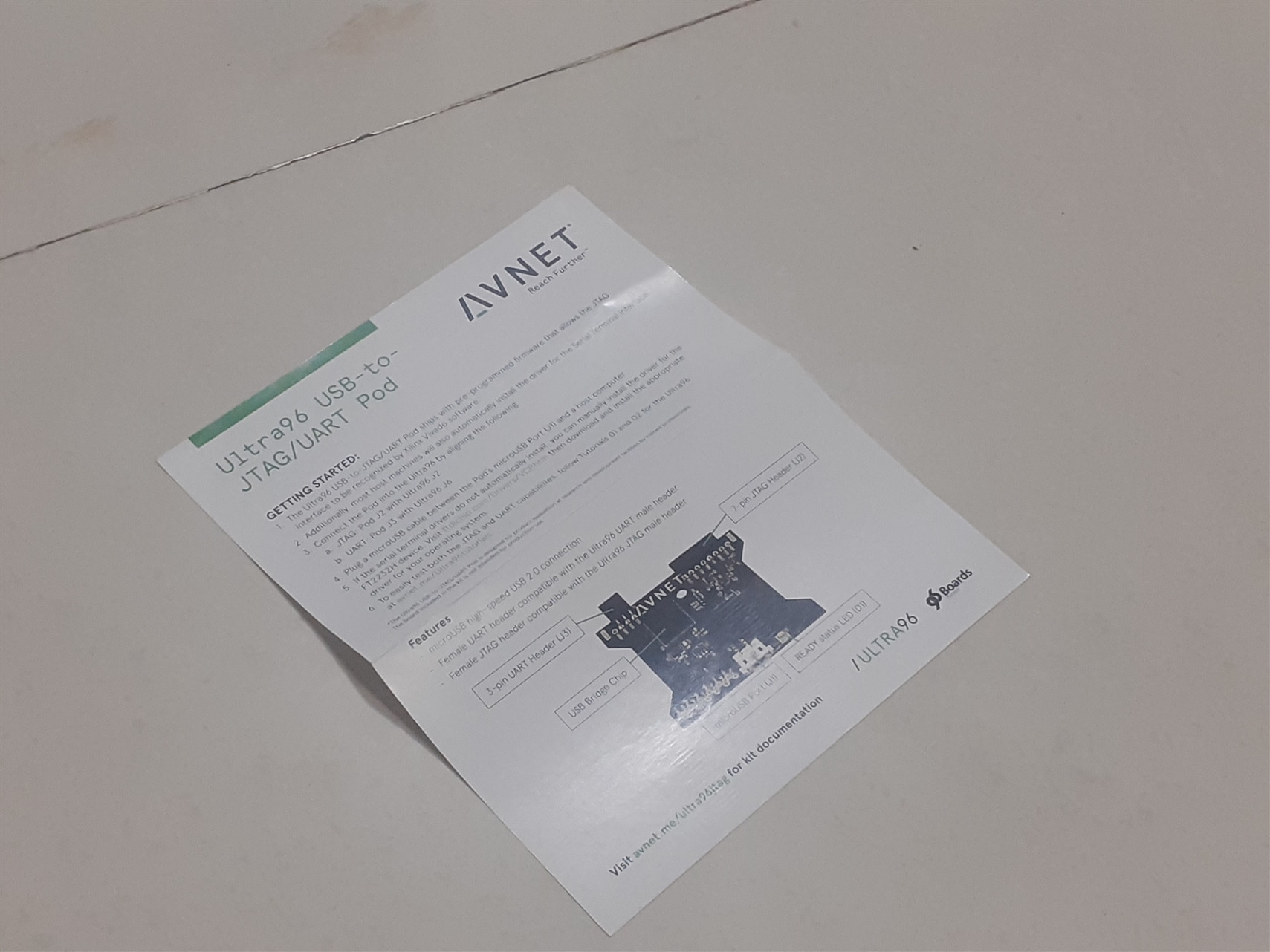
Ultra96 USB-to-JTAG/UART Pod

Things included in the USB-to-JTAG/UART Pod Box:-
USB to JTAG/UART pod
USB to JTAG/UART operating manual
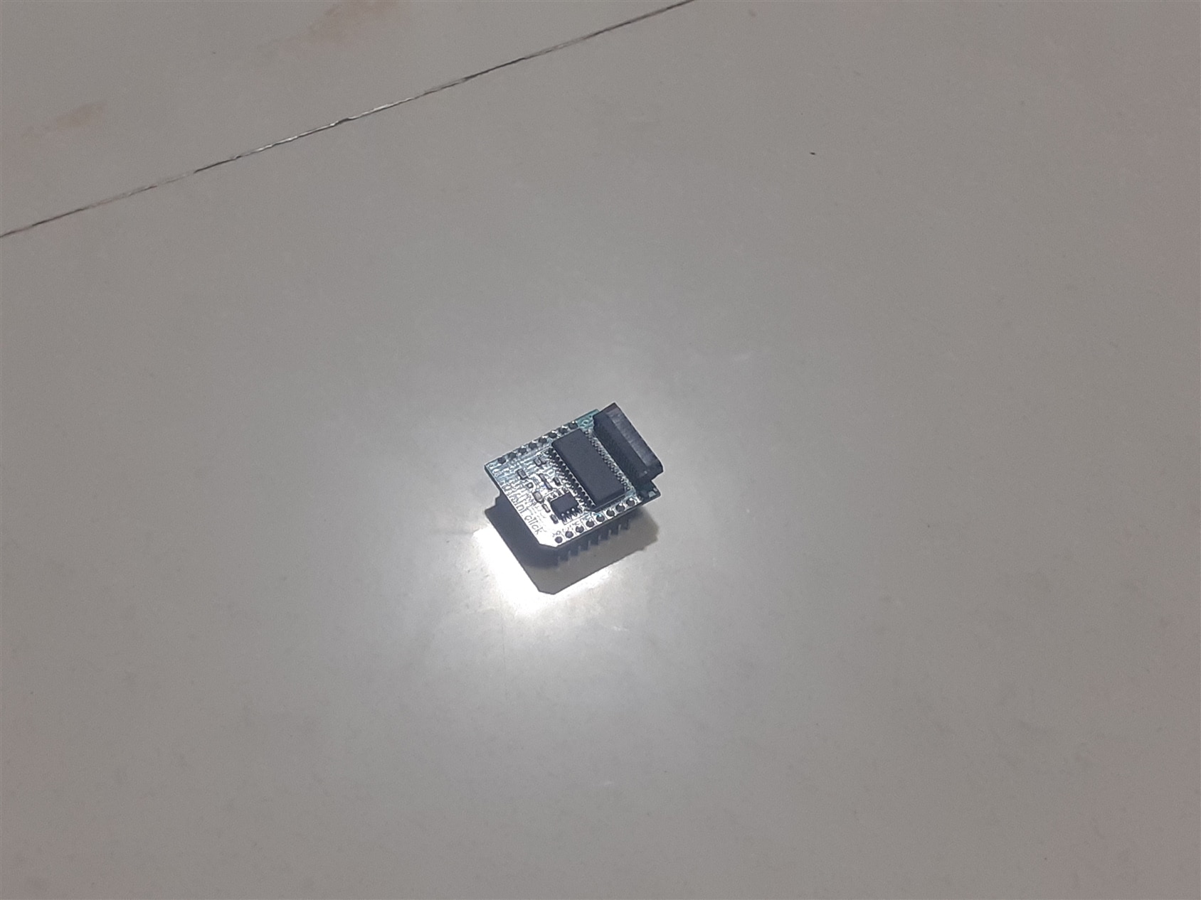
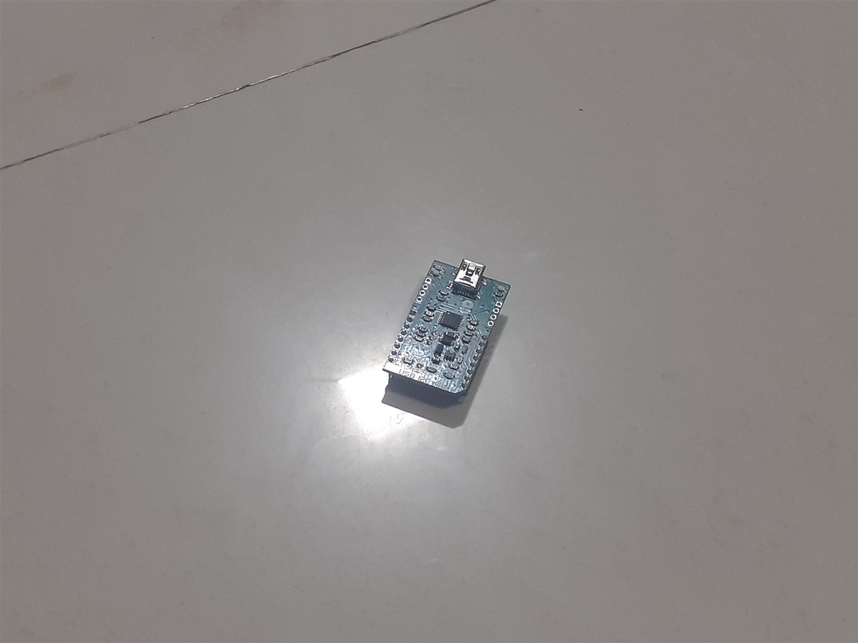
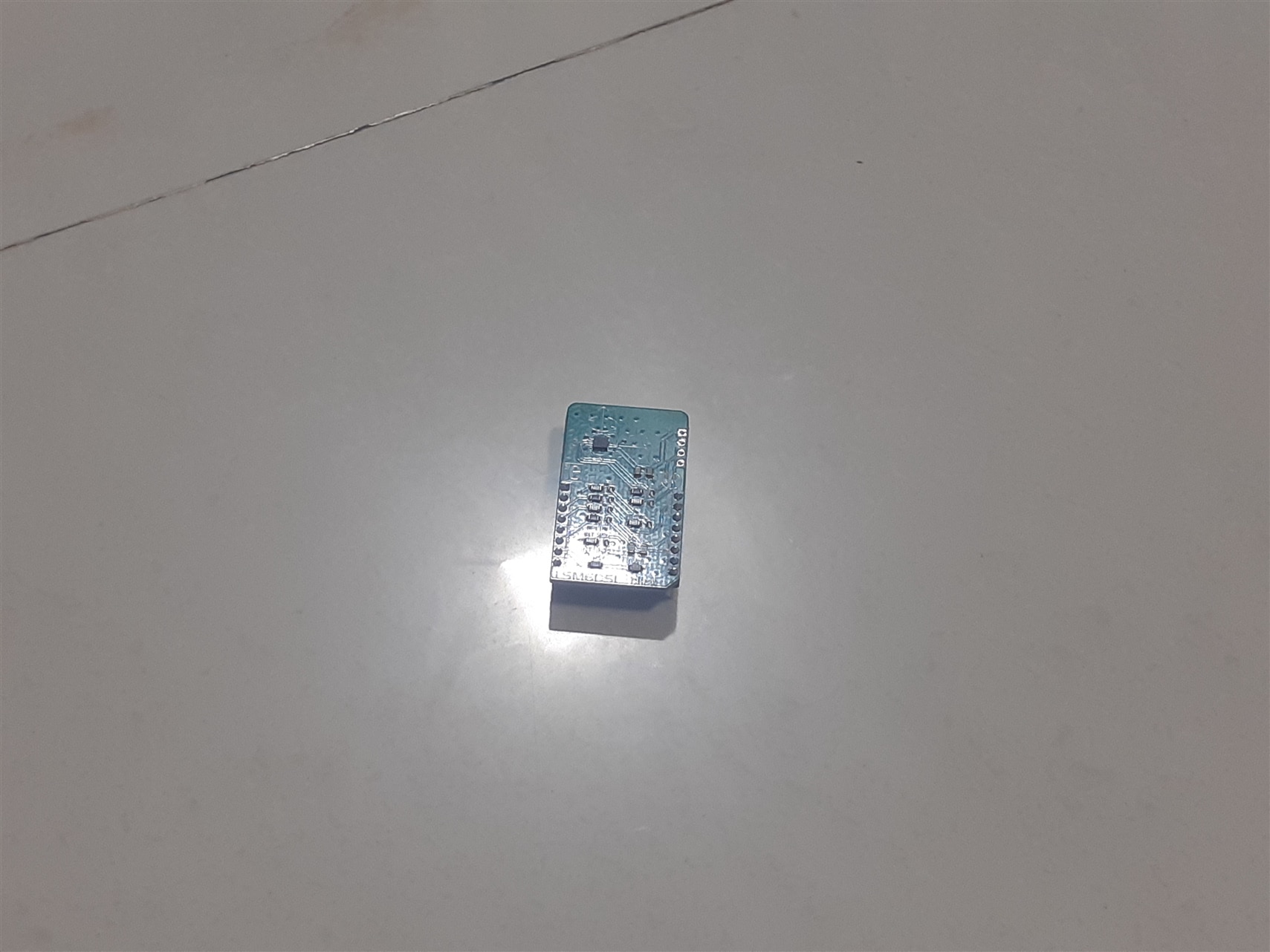
96Boards Click Mezzanine Starter Kit
Things included in the 96Boards Click Mezzanine Starter Kit box
List of available click board price list (This is very interesting price list that can be used for future project making)
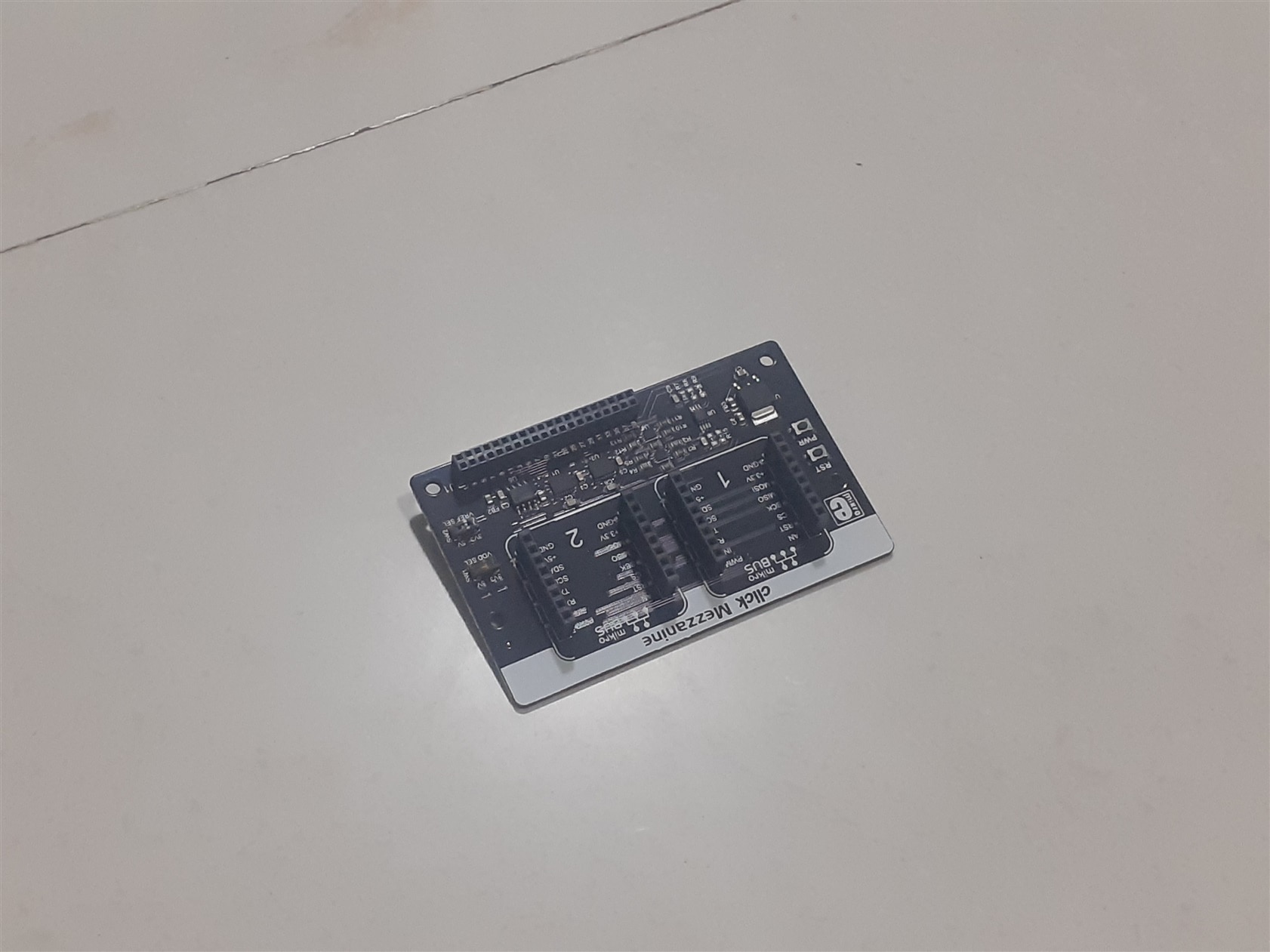
Click mezzanine board
LCD
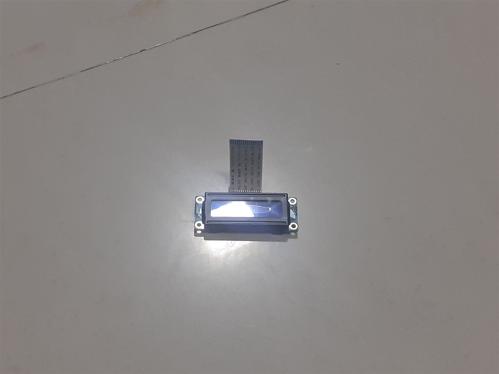
LCD board
USB to I2c
accelerometer
Free Vivado Design Edition License

Installation of software libraries and building a simple project
Writing LINUX ISO on SD card:-
For writing LINUX ISO on 16 GB SD card you have to download the LINUX ISO from the following link “avnet.me/ultra96-v2-oob”. After you open the link on the web browser you will see the webpage as shown on figure 1.1
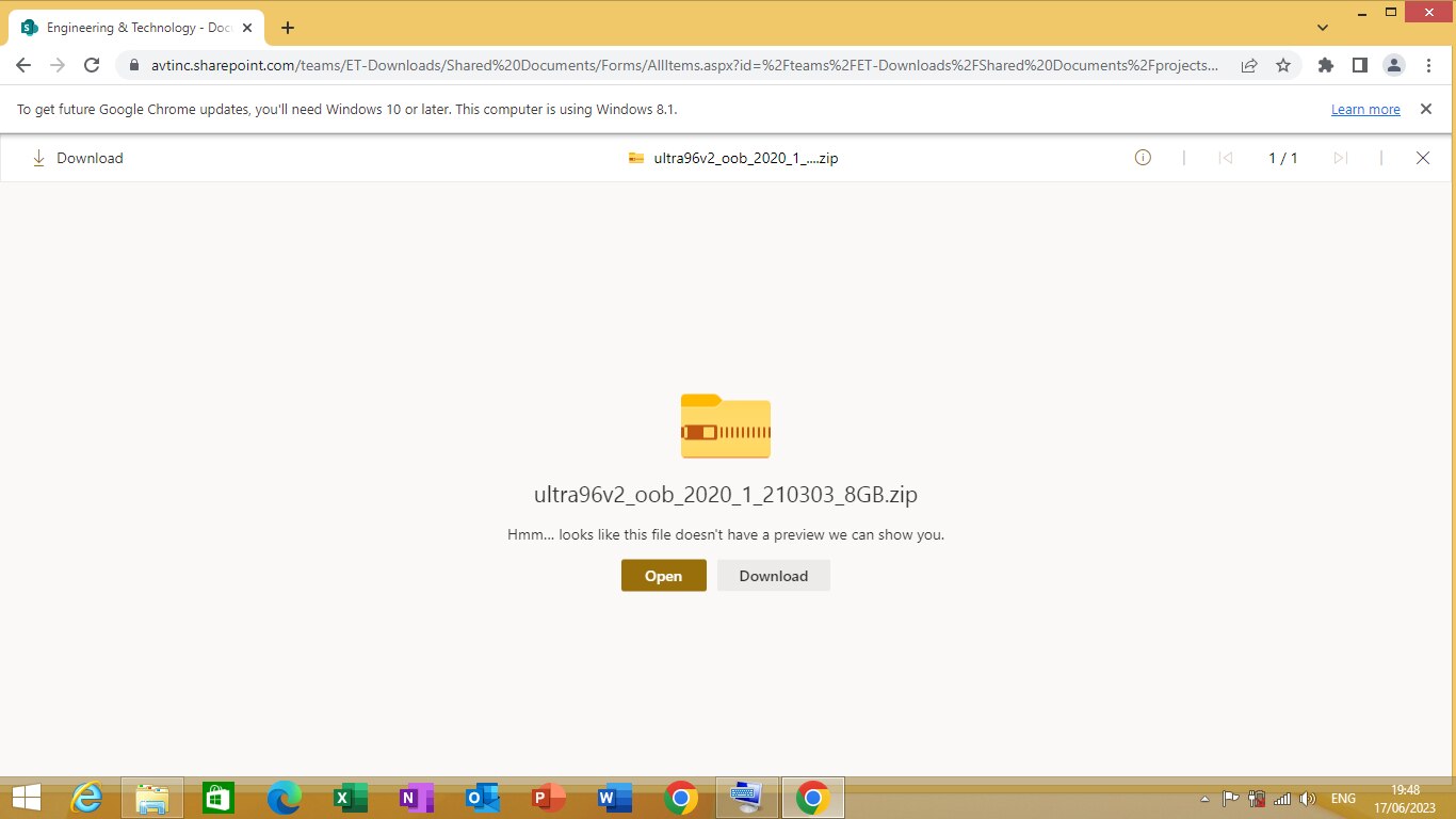
Figure 1.1
Click on ‘Download’ to download the ISO. After downloading the ISO you need to write that ISO on SD card provided using etcher program. I will be using balena etcher
Downloading BalenaEtcher Program
To download BalenaEtcher Program. Open the following link on the web browser “etcher.balena.io”. A webpage will be opened as shown on figure 2.1 bellow.
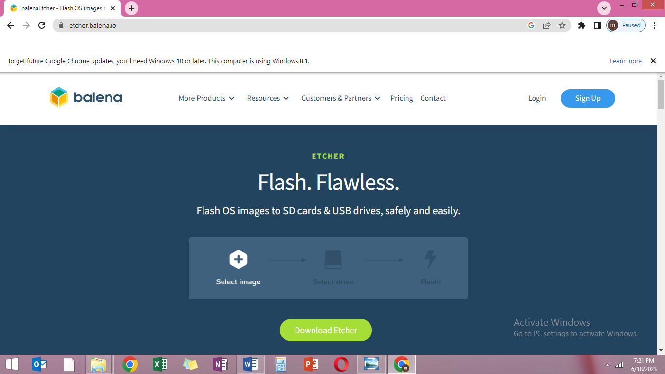
Figure 2.1
Click on “Download Etcher” to download the etcher program.
(Note:- Etcher program will write on boot sector of the SD card. It’s purpose is to make SD card bootable. It write image files such as .img, .iso and zipped folder creating SD card bootable)
Installing BalenaEtcher Program
To install the ‘balenaetcher’ program, double click on the ‘balenaetcher setup’ as shown in figure 3.1
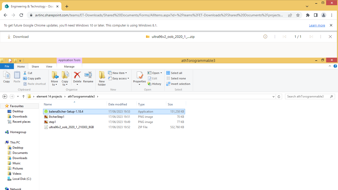
Figure 3.1
It will open a dialog box with license agreement as shown on Figuer 3.2. click on I agree to continue the setup.
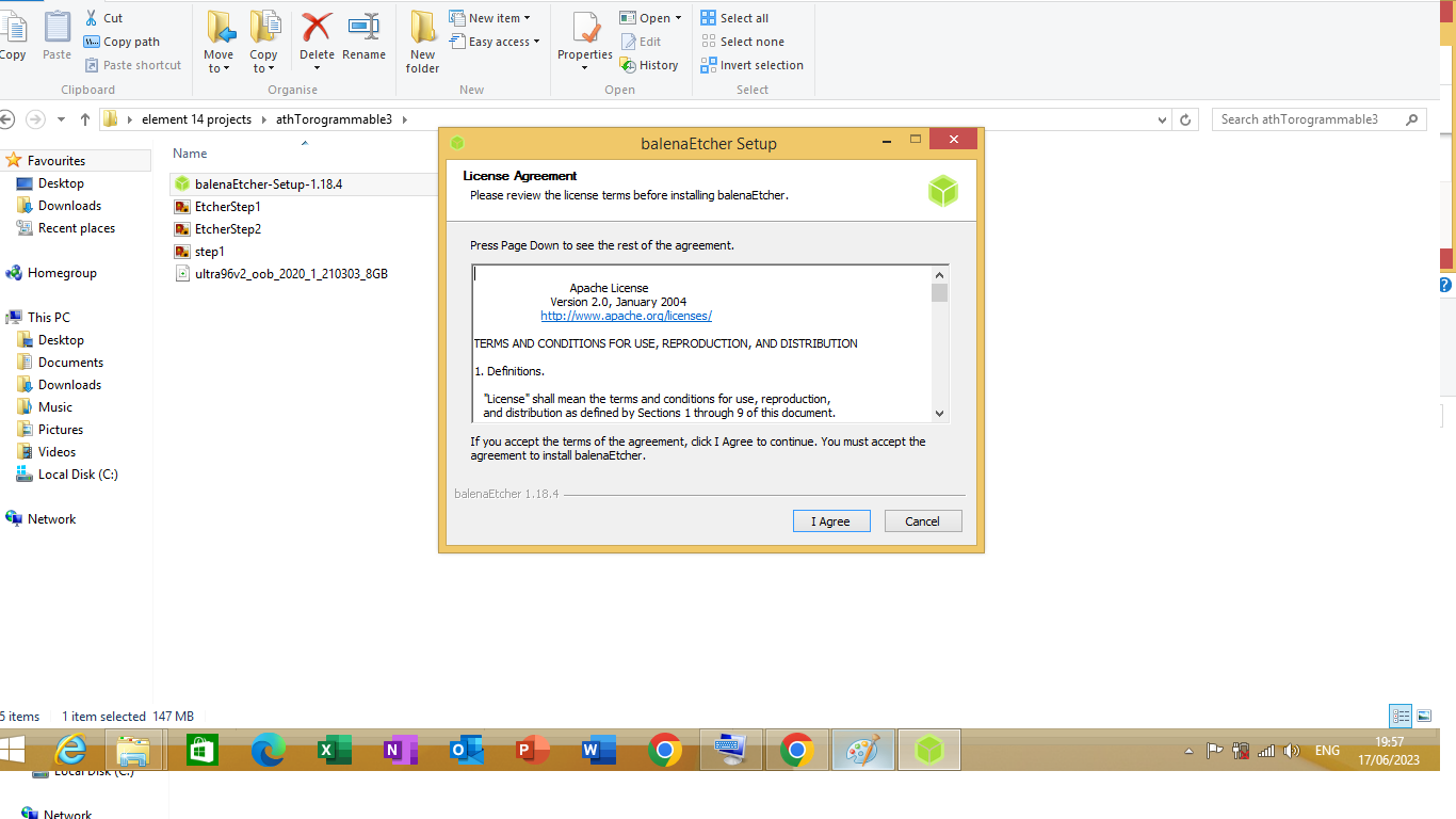
Figure 3.2
Installation process will start as shown in Figure 3.3
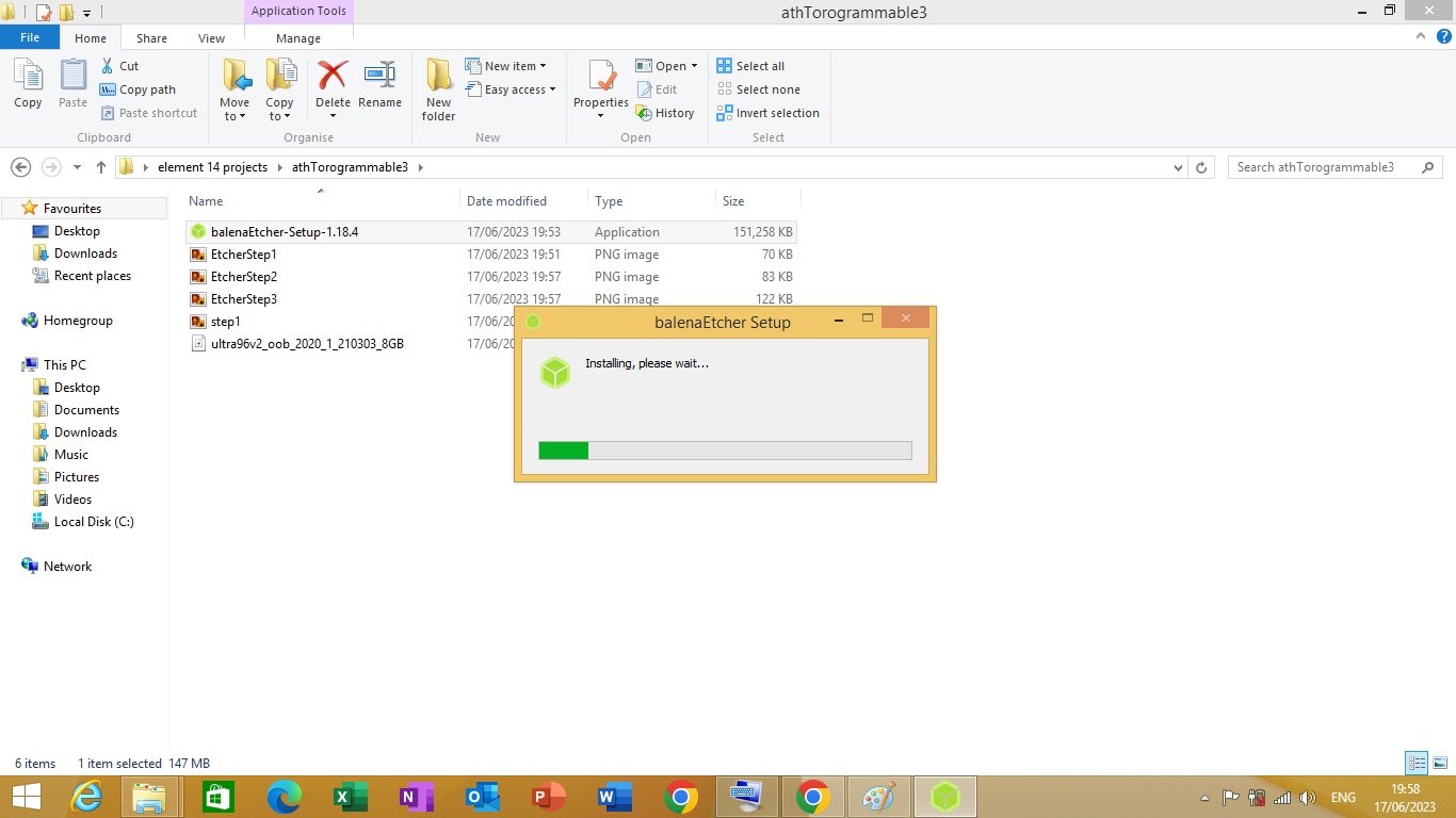
Figure 3.3
Once the installation process is complete you can open the BalenaEtcher application by double clicking on BalenaEtcher desktop icon on your desktop.
Writing OS image using BalenaEtcher Program
Insert the 16 GB SD card provided with the Ultra96_V2 development kit on the SD card slot.
Double click on BalenaEtcher Application on your desktop to open the application .The program will start as shown in Figure 4.1
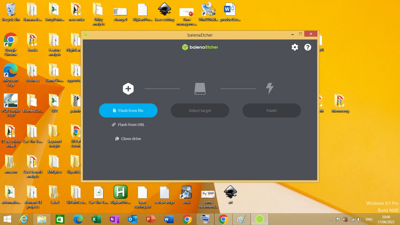
Figure 4.1
Click on ‘Flash from file’ button on the application it will open an open window dialog from where you have select the OS image that you want to write on SD card as shown in figure 4.2 .
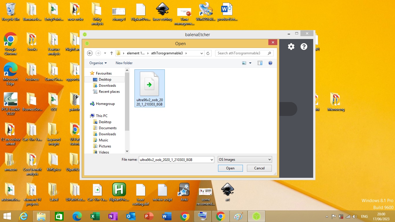
Figure 4.2
Click on ‘ultra96v2_oob_2020’ and than click open to open the file. After you open the file the balenaEtcher will automatically open Select Target dialog box as shown in Figure 4.3.
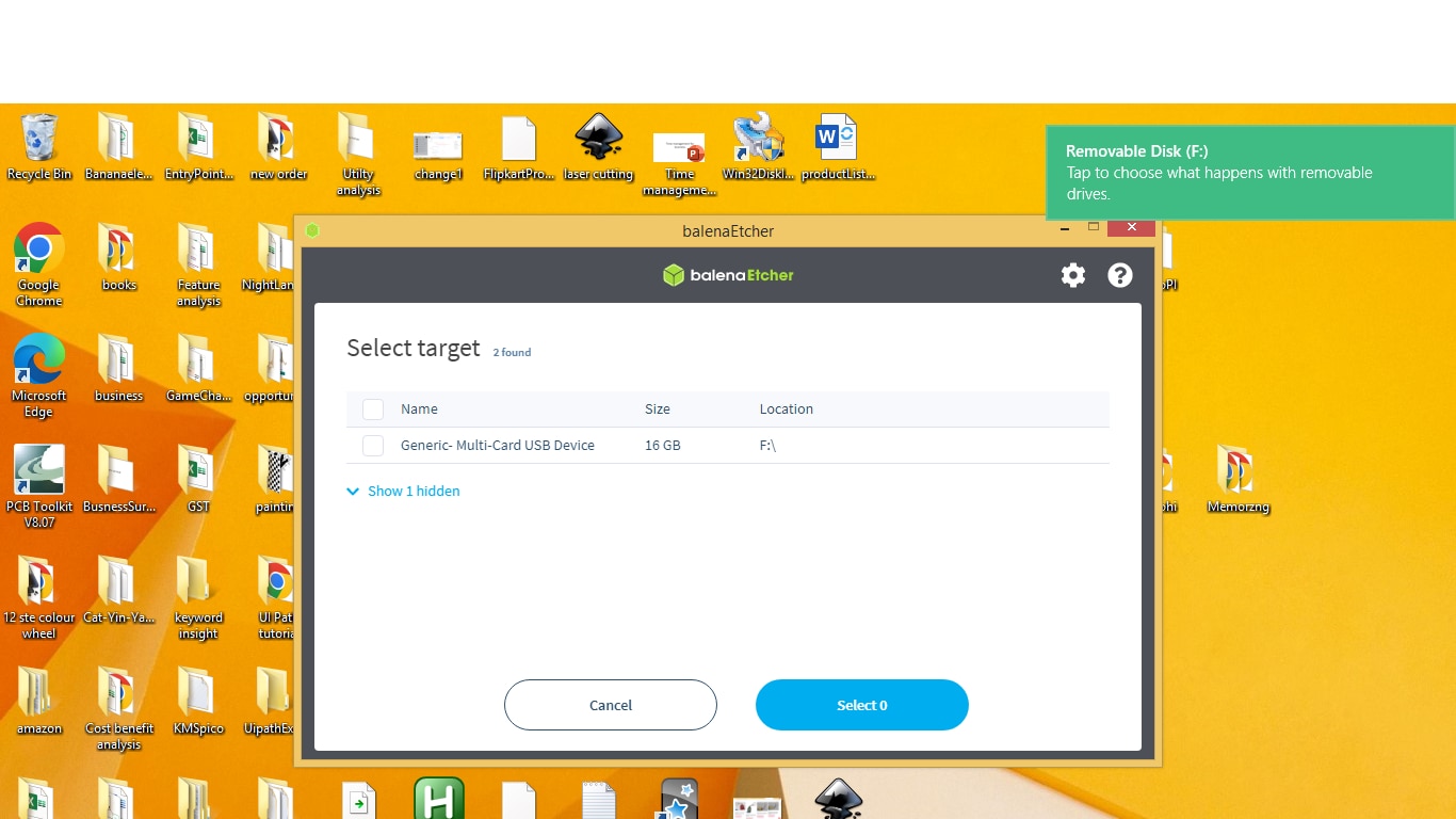
Figure 4.3
Check on ‘Generic Multi-Card USB Device’ as shown on Figure 4.4
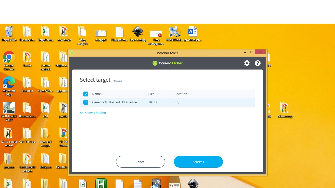
Figure 4.4
After checking the ‘Generic Multi-Card USB Device’ click on ‘select 1’ button on the dialog box. After clicking on the button the application will open a dialog box where it will ask you to flash the card. Click on the ‘Flash’ button to flash the card as shown on Figure 4.5.
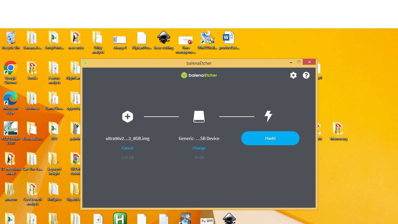
Figure 4.5
After clicking on ‘Flash’ button on the application the application will start flashing the card as shown in Figure 4.6 .
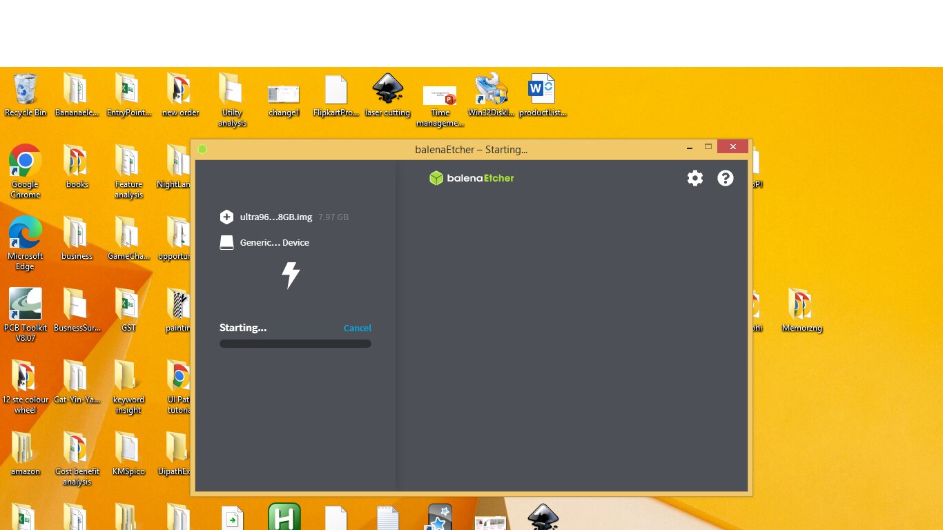
Figure 4.6
Flashing operation started as shown in Figure 4.7

Figure 4.7
After flashing is completed the program will do a validation operation as shown in Figure 4.8

Figure 4.8
After validation the program will do the finishing step as shown in Figure 4.9
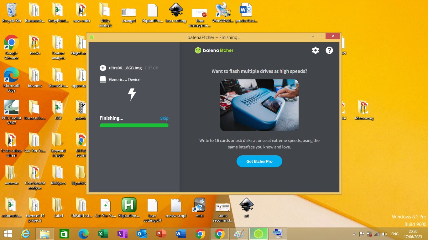
Figure 4.9
After the flash is finished it will show a dialog box that states the flash is finished as shown in Figure 4.10
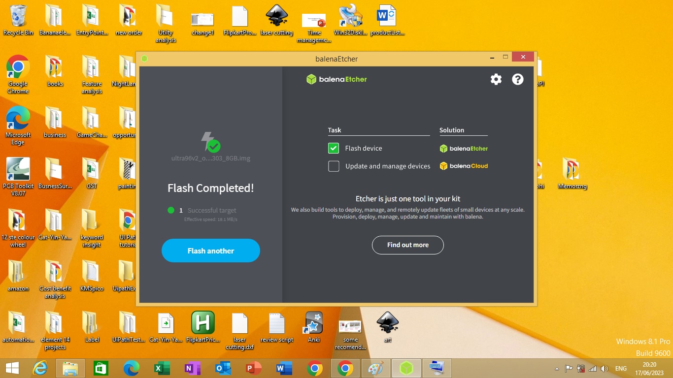
Figure 4.10
After the flashing operation is finished you can remove the SD card from the SD card Slot as Operating System is flashed on the card. Your card is ready to be inserted into the SD card slot of Ultra96-v2 development board with the linux operating system in it.
Getting started with Ultra96-V2 development board
Booting the Ultra96-V2 development board
To boot the Ultra96-V2 development board. First insert the SD card that is been flashed with the Linux Operating System on the SD card socket of Ultra96-V2 development board. Than configure the boot switch to SD card boot as shown in Figure 5.1
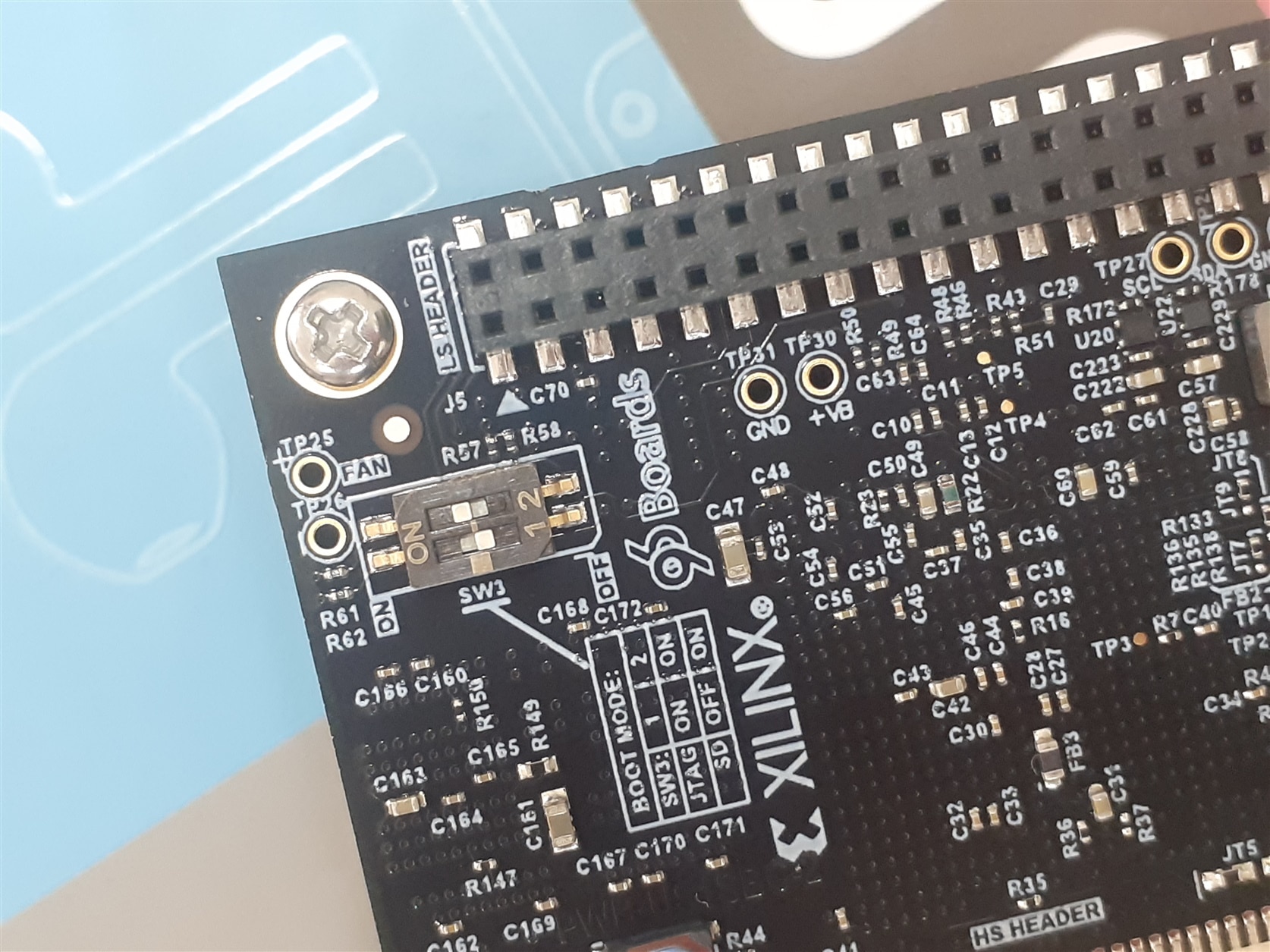
Figure 5.1
After configuring the boot switch connect the 12 volt supply to the Ultra 96-V2 board as shown in Figure 5.2
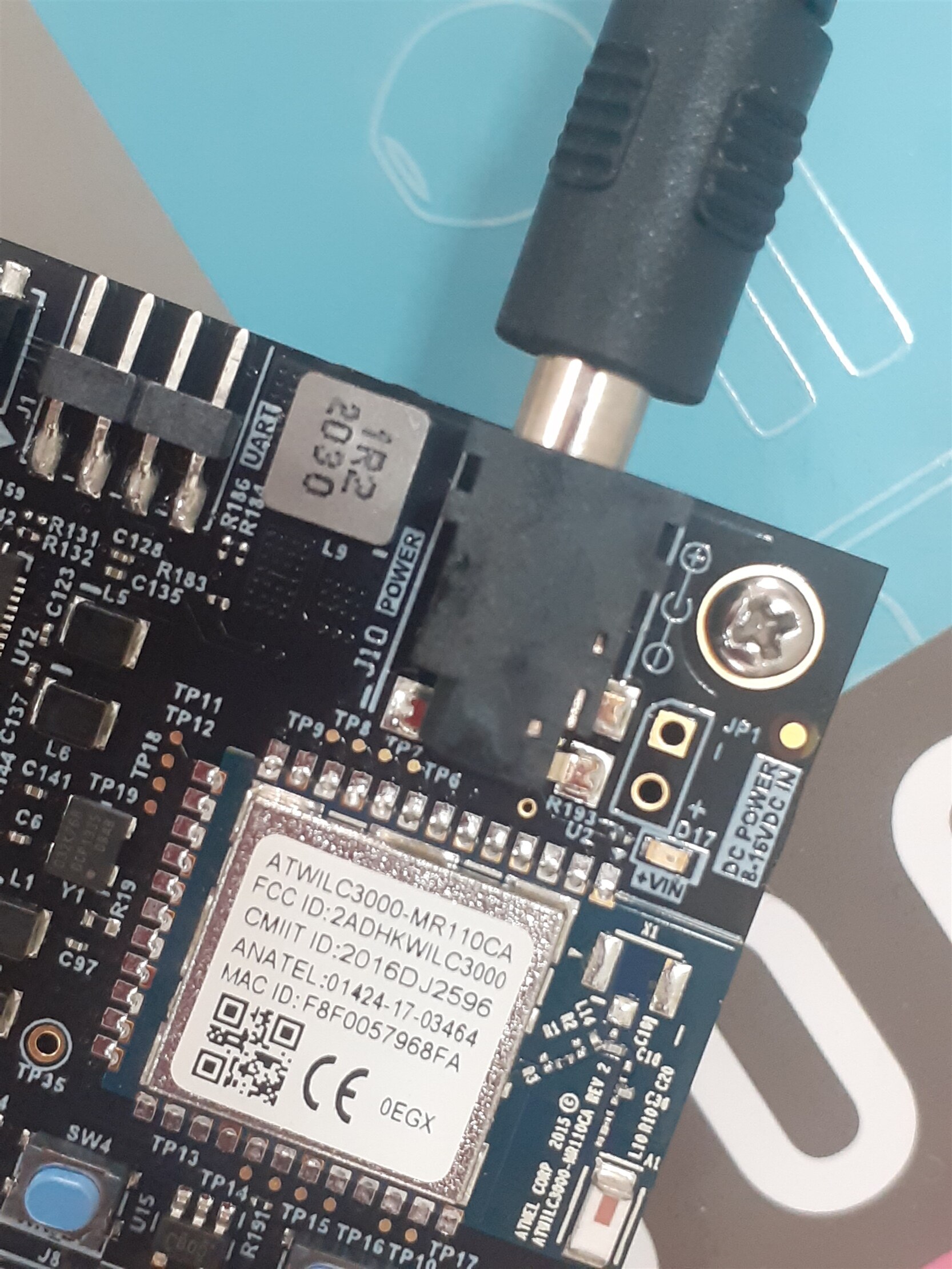
Figure 5.2
When you switch on the power the green light on the Ultra96-V2 board will illuminate as shown in Figure 5.3
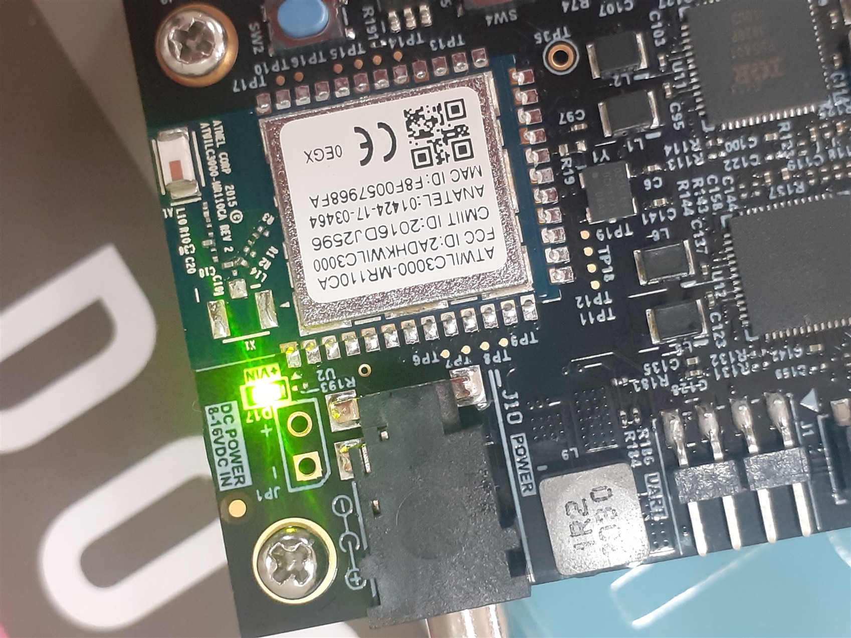
Figure 5.3
To boot the Ultra96-V2 board press and release the power button switch (SW4) as shown in Figure 5.4.

Figure 5.4
The Green Power LED (D2). Red INIT_B LED (D5) and the Green User LEDs should illuminate. After a few seconds. INIT_B LED will turn off and the Blue DONE LED (D1) will illuminate. As shown in figure 5.5
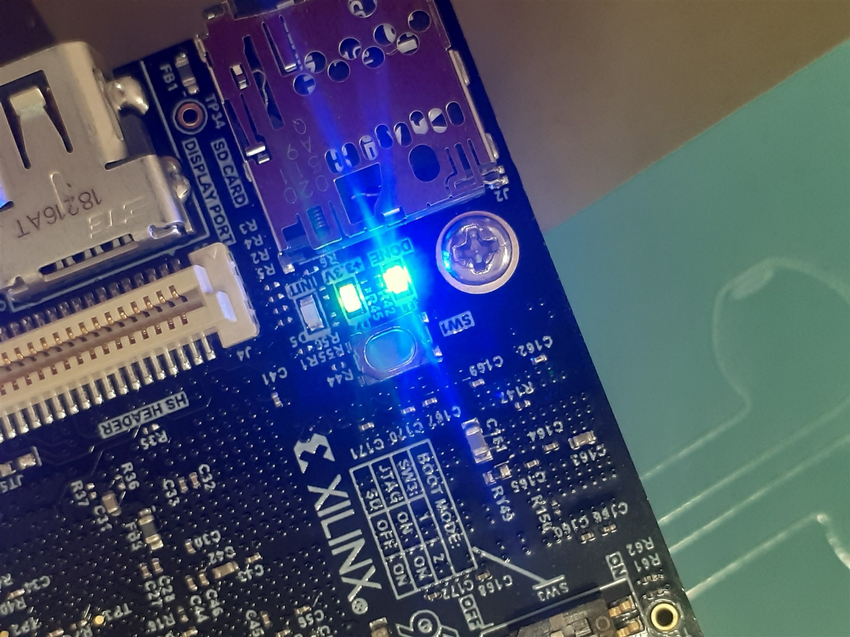
Figure 5.5
The Ultra96-V2 has now booted Linux and several experiments are possible.
To shutdown, press and release the power button (SW4) to initiate a shutdown sequence as shown in figure 5.6
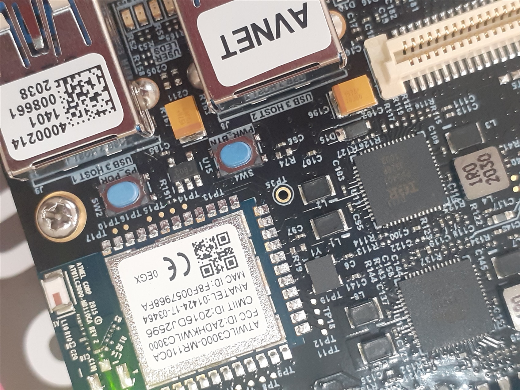
Figure 5.6
Setting up environment for Ultra96-V2 development board
We will wirelessly connect to the Ultra96-V2 development board and play with some of LED’s of the board by switching them on or off. When the Linux boots the development board the Linux configures the board to works as a Webserver which can be accessed via Wi-Fi. The Wi-Fi name of the board is “Ultra96-V2_<MAC ADDRESS> ”. To access the board via Wi-Fi, login to the board via laptop or desktop using Wi-Fi by connecting to the “Ultra96-V2_<MAC ADDRESS> ” as shown in Figure 6.1
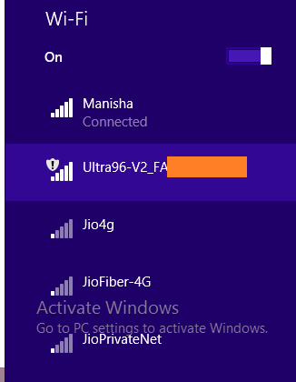
Figure 6.1
Connect to the “Ultra96-V2_<MAC ADDRESS> ” via Wi-Fi using laptop or desktop. After connecting to the Ultra96-V2 development board webserver. open a browser on the connected machine, and browse to the IP address of the board, which is http://192.168.2.1. The browser page will show like Figure 6.2.

Figure 6.2
The LED we are going to play with are D3, D4, D6, and D7 as shown in Figure 6.3
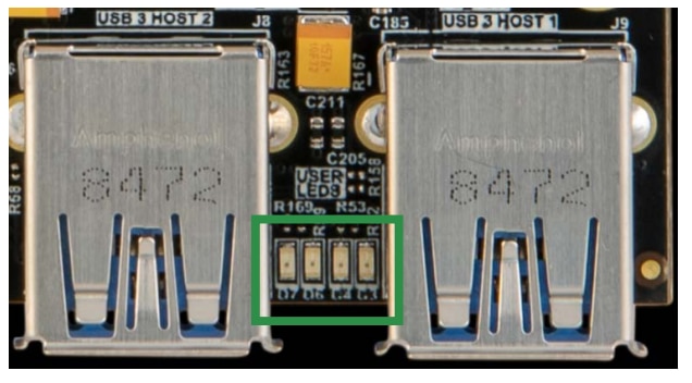
Figure 6.3
The project that allows us to play with D3, D4, D6, and D7 LED is known as “Ultra96-V2 GPIO LEDs” as shown in Figure 6.4
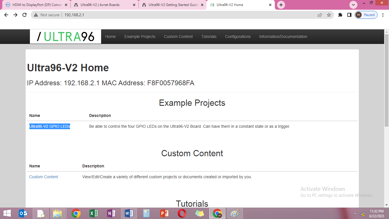
Figure 6.4
Click on the “Ultra96-V2 GPIO LEDs” project to start the project as shown in Figure 6.5
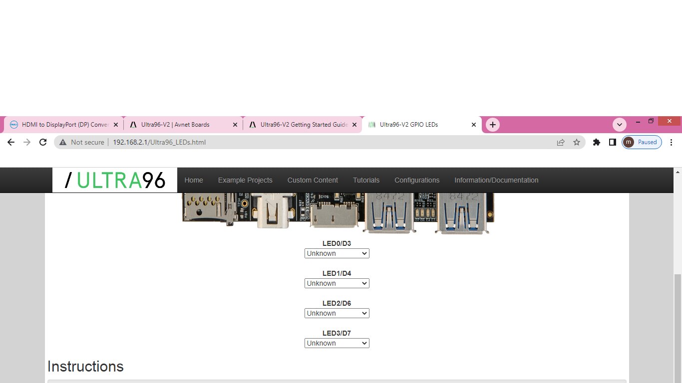
Figure 6.5
You can change the status of the LED by using drop down menu for each LED. You can turn LED ON/OFF or you can use it to show status of various resources in the development board. Figure 6.6 depicts how to turn on the LED.
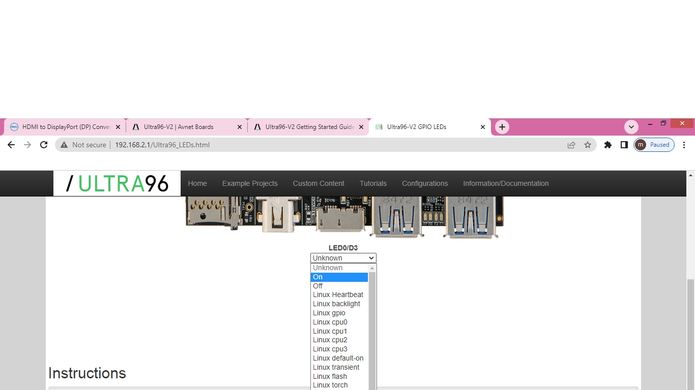
Figure 6.6
Things that didn’t worked with Ultra96-V2 development board
Mini-Display port to HDMI interface problem
After setting up the board for Linux and booting up the board with linux. I tried to connect the board to the monitor using Mini-Display port to HDMI convertor cable as shown in Figure 7.1

Figure 7.1
The cable cost me around 4 dollar. I tried to connect the Ultra96-V2 development board with the monitor no display. After reading the Getting started guide they say that they need Active Mini-Display port to HDMI convertor cable. Which is very expensive around 400 euro out of my budget.
Link:- https://www.startech.com/en-eu/audio-video-products/hdvgadp2hd
What is Active Adapter: ?
DisplayPort signaling is 3.3 volts ,while HDMI/DVI signaling is 5 volts so some active conversion is always required. I think implementers picked up on the word “active” and figured that since there is a spec for an adapter with an “active protocol converter”, any adapter without that converter ought to be called “passive”.
truly “active” adapters that do not rely on DisplayPort++/Dual-Mode at all. Instead they are able to decode the LVDS DisplayPort packet protocol in real-time and re-encode it into HDMI/DVI compatible TMDS protocol. DisplayPort->Dual-link DVI-D adapters are true “active” adapters. As are “EyeFinity” certified adapters and any adapter with HDMI 2.0 support. Some active adapters need to be powered by a USB port, however, most adapters available today are powered by pin 20 on the DisplayPort source which supplies 3.3 volts at up to 500mA. These truly active adapters are more expensive but allow more flexibility with refresh rates and resolutions depending on which integrated circuit is used inside.
What are Active or Passive Adapters ?
Type-2 adapters also pass-through the existing TMDS signal and level shift it from 3.3v->5v, but include more advanced integrated circuits and are able to operate at up to 300MHz with HDMI thus enabling 4K@ 30Hz output per HDMI 1.4 spec. Depending on the vendor, these adapters may be marketed as “active” or “passive” so you really need to read the fine print to understand the specs of the adapter.
What are passive adapters ?
The “Type-1” adapters which are commonly sold as “passive” rely on the DisplayPort source (like a video card) supporting DisplayPort++ (aka Dual-mode). When certain pins are pulled up to 3.3 volts or down to ground through specific resistor values, the physical DisplayPort pins are programmed to output the HDMI/DVI TMDS protocol instead of the LVDS DisplayPort packet protocol. But the TMDS protocol is still output at 3.3 volts which won’t work with a DVI/HDMI monitor designed for 5 volts. So the type-1 adapters include active electronics to level shift the 3.3 volt signaling to 5 volts. The signaling is limited to 165MHz bandwidth so screen refresh rates and resolutions are limited too. Aside from the level shifters, additional electronics are needed to regulate power – typically the 3.3 volts supplied from the DisplayPort connector on pin 20 is boost-converted to 5 volts. There is also a circuit to handle the DDC communications as well. So there is a lot of stuff inside your “passive” DisplayPort adapter.