


Table of Contents
The MAX7219 Peripheral
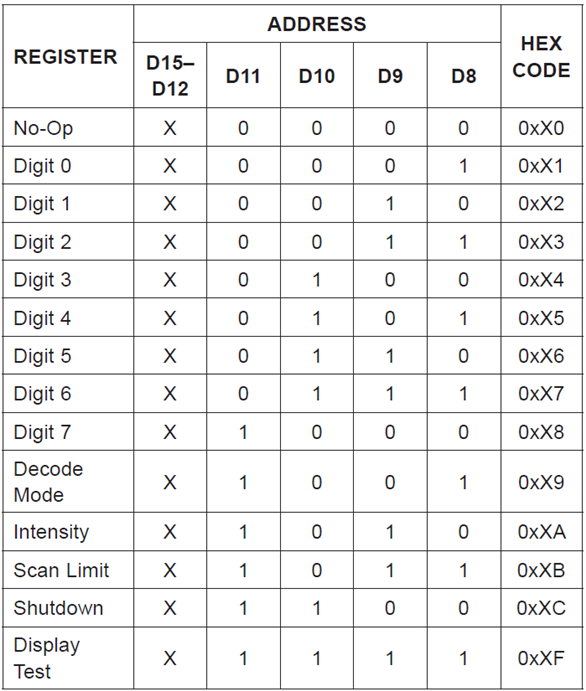
The MAX7219 IC is a "Serially Interfaced 8-Digit LED Display Driver", which interface is based on SPI, with an specific protocol for configuration and data management. According to the datasheet, the IC starts with all registers in reset state and the data registers in blank. This means that the display will show nothing when it is powered up. The Address Map connotes that we could have other processor, but the state machine brings the behavior of the system according data handled in the SPI communication.

You must start the communication, send the register to be modified, and the data to be recorded. This brings data representation over 7 segment displays. Remember that the MAX7219 has a power and logic levels of 5V, but don't worry, you can change the voltage levels on the Mezzanite board using the VDD SEL switch. The VREF SEL changes the analog reference for the ADC.

The Software
The new software must be able to encode and send the information to the device since the SPI peripheral only stablishes the communication port, but not the correct interpretation of the information. This think carries the following header file.
#ifndef __MAX7219_H__
#define __MAX7219_H__

#define MAX72XX_NOP			0x00
#define MAX72XX_D0			0x01
#define MAX72XX_D1			0x02
#define MAX72XX_D2			0x03
#define MAX72XX_D3			0x04
#define MAX72XX_D4			0x05
#define MAX72XX_D5			0x06
#define MAX72XX_D6			0x07
#define MAX72XX_D7			0x08
#define MAX72XX_DECODE		0x09
#define MAX72XX_INTENSITY	0x0A
#define MAX72XX_SCAN		0x0B
#define MAX72XX_SHUTDOWN	0x0C
#define MAX72XX_TEST		0x0F

#include <stdint.h>
#include "xspips.h"

void clearDisplay(XSpiPs *Spi);
void DecodeInt(XSpiPs *Spi, uint16_t number);
void sendCommand(XSpiPs *Spi, uint8_t cmd, uint8_t val);
void displayInit(XSpiPs *Spi, u8 scanLimit);

#endif
here, all the available commands on the MAX7219 are defined by macros. We must include the xspips.h since there are the definitions of the SPI controller on that archive. The definitions of each function are shown below.
#include "MAX7219.h"
#include <math.h>

void clearDisplay(XSpiPs *Spi){
	for(int d = 7; d >= 0; d--){
		sendCommand(Spi, d + 1, 0x0F);
	}
}

void DecodeInt(XSpiPs *Spi, uint16_t number){
	static u8 nDigits;
	static u16 IntConditioner;
	nDigits = ceil(log(number)/log(10));
	IntConditioner = number;
	static double IntMultiplier;
	clearDisplay(Spi);
	for(int d = nDigits - 1; d >= 0; d--){
		IntMultiplier = pow(10, d);
		IntConditioner = number/IntMultiplier;
		number -= IntConditioner*IntMultiplier;
		sendCommand(Spi, d + 1, IntConditioner);
	}
}

void sendCommand(XSpiPs *Spi, uint8_t cmd, uint8_t val){
	static u8 dummy[2];
	static u8 CmdData[2];
	CmdData[0] = cmd;
	CmdData[1] = val;
	XSpiPs_PolledTransfer(Spi, CmdData, dummy, 2);
}

void displayInit(XSpiPs *Spi, u8 scanLimit){
	sendCommand(Spi, MAX72XX_SCAN, scanLimit);
	sendCommand(Spi, MAX72XX_DECODE, 0xFF);
	sendCommand(Spi, MAX72XX_SHUTDOWN, 1);
	sendCommand(Spi, MAX72XX_TEST, 0);
	sendCommand(Spi, MAX72XX_INTENSITY, 5);
	clearDisplay(Spi);
}
As you can see, the math.h header file isbeing used. As you may know, the math library is not considered an API like other files, it is refered to as an ABI and this library should be linked with the project. To do this, the developer needs to add the -lm flag through the C/C++ Settings GUI, located on the project properties.


After that, you will be able to compile without any errors.
The main code consists of the SPI controller initialization, MAX7219 initialization, and data encoding representation. With this in mind, the following code solves this logic,
#include <stdio.h>
#include "platform.h"
#include "xil_printf.h"
#include "xspips.h"
#include <sleep.h>
#include "MAX7219.h"

int main(){
    init_platform();
    int Status;
    XSpiPs Spi;
    XSpiPs_Config *SpiConfig;
    print("MAX7219 numerical decoding\r\n");
    SpiConfig = XSpiPs_LookupConfig(XPAR_XSPIPS_0_DEVICE_ID);
    if (NULL == SpiConfig) {
    	xil_printf("Error initializing device.\r\n");
    	while(1){}
    }
    Status = XSpiPs_CfgInitialize(&Spi, SpiConfig, SpiConfig->BaseAddress);
    if (Status != XST_SUCCESS) {
    	xil_printf("Error initializing device configuration.\r\n");
    	while(1){}
    }
    XSpiPs_SetOptions(&Spi, XSPIPS_MANUAL_START_OPTION | \
    			XSPIPS_MASTER_OPTION | XSPIPS_FORCE_SSELECT_OPTION);
    XSpiPs_SetClkPrescaler(&Spi, XSPIPS_CLK_PRESCALE_8);
    XSpiPs_SetSlaveSelect(&Spi, 1);
    displayInit(&Spi, 7);
    u16 counter = 1;
    while(1){
    	DecodeInt(&Spi, counter++);
    	xil_printf("%u decoded.\r\n", counter);
    	sleep_A53(1);
    }
    return 0;
}
From the last code in Blog 3, you may see that the code has been reduced to a minimum to be functional and a counter variable updates the data to be displayed.
Result
The practical behavior has a small logic error on small numbers, less than or equal to ten, but it represents in an acceptable way the information generated by the one second delay in counting. You can see this in the video below.
Finally, each time that the information is decoded, the processor informs about this event,

If you have any recommendations please, don't hesitate to let me know.
