


1. Introduction
In the last blog, we just used the Processing System (PS) side to blink the 4 user programmable LEDs, so we will build on that and see how we can incorporate the PL side LEDs and extend our design to use both the PS and the PL. In this blog we will try to replicate the flashing lights of a police car lights using the Ultra96v2 FPGA board.
All the files for this blog are available here: https://github.com/rajivbishwokarma/element14_p2p_blogs
2. Setting up hardware in Vivado
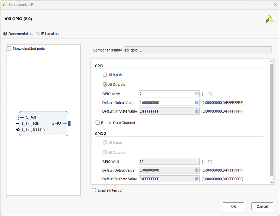
The block design is a very simple block design using an external GPIO port connected to the Zynq US+ block through the AXI GPIO IP. Figure 1 shows the complete block design for the system.

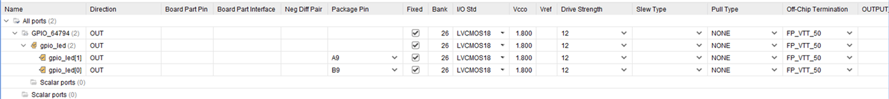
Once this is done and the design is validated to have no error, then we can go ahead and assign the physical PIN locations to our “gpio_led[1:0]” signal as shown in Figure 3. The pins that we are using are used by Wi-Fi and Bluetooth on-board for their ready signals, however, since we are not actually using the Wi-Fi and Bluetooth in this design, it is safe to access them through our design. Please note that we cannot use these LEDs if we have either the PYNQ or the PetaLinux designs.
Once we do this and save the constraints file, we can then generate the bitstream for the design. Then we can export the hardware design so that later on we will import that design to Vitis in order to enable the clock signal as Ultra96v2 does not provide a direct access to clock from the PL side.
3. Blinking the LEDs using Vitis
We can then import the hardware platform that we exported through Vivado and create a hello world application in Vitis. Then, in place of just printing hello world, we can use the following code to blink the LEDs.
#include <stdio.h>
#include "platform.h"
#include "xil_printf.h"
#include "xgpio.h"

#define GPIO_ID XPAR_GPIO_0_DEVICE_ID
#define LED_CHAN 1		/* GPIO Channel */
#define DELAY 100000000	/* 100MHz clock*/


/* Create an instance of the GPIO */
XGpio gpio;

int main()
{
	int status;
	volatile int delay;
    init_platform();

    status = XGpio_Initialize(&gpio, GPIO_ID);
    if (status != XST_SUCCESS)
    	return XST_FAILURE;

    while(1){
    	XGpio_DiscreteWrite(&gpio, LED_CHAN, 0x01);

    	for (delay = 0; delay < DELAY; ++delay);

    	XGpio_DiscreteWrite(&gpio, LED_CHAN, 0x02);

    	for (delay = 0; delay < DELAY; ++delay);
    }

    cleanup_platform();
    return 0;
}
4. Result
We then build the project and then run the application on hardware. Then, we will get the police lights flashing as you can see in the video below.
YouTube: https://youtu.be/J5f8HpWGUiw
5. Conclusion
Creating a simple LED flashing design on the Ultra96v2 board using both the PS and PL is both fun and educational. It offers a glimpse into the world of FPGA design and the potential of the Ultra96v2 board. This police light simulation is just the tip of the iceberg. In the next blog, we will again blink LEDs using PL but rather than just using Vivado and Vitis, we will use PYNQ.

