


AMD Vitis unified software platform
Some question with respect to AMD vitis unified development platform
What is AMD Vitis unified development platform ?
The Vitis unified software platform is an integrated development environment (IDE) for the development of embedded software applications targeted towards Xilinx® embedded processors. The Vitis software platform works with hardware designs created with Vivado® Design Suite. The Vitis software platform is based on the Eclipse open source standard.
Why should we use Vitis over other platform ?
If you are interested in FPGA accelerated application targeted to either Data Center accelerator cards or Embedded Processor platforms.
What are the two component of Vitis accelerated application ?
- a software program running on a standard processor such as an X86 processor, or ARM embedded processor
- AMD device binary (xclbin) containing hardware accelerated functions, or kernels.
What is the software program in in Vitis Programming ?
The software program, or host application, is written in C/C++ and runs on a conventional CPU. The software program uses the XRT native API implemented by the AMD Runtime library (XRT) to interact with the acceleration kernel in the AMD device.
What is hardware accelerated kernels in vitis programming ?
The hardware accelerated kernels can be written in C/C++ or RTL (Verilog or VHDL) and run within the programmable logic part of the AMD device. The kernels are integrated with a Vitis hardware platform using standard AXI interfaces.
Working of Vitis accelerated applications on Data Center or Embedded Processor acceleration platforms ?
- On Data Center accelerator cards, the software program runs on an x86 server and the kernels run in the FPGA on a PCIe®-attached acceleration card.
- On Embedded Processor platforms, the software program runs on an Arm processor of an AMD MPSoC device and the kernels run within the same device.
What is simplest way to make the software program interact with the hardware kernels?
- The host application writes the data needed by a kernel into the global memory of the FPGA device.
- The host program sets up the input parameters of the kernel.
- The host program triggers the execution of the kernel.
- The kernel performs the required computation, accessing global memory to read or write data, as necessary. Kernels can also use streaming connections to communicate with other kernels, passing data from one kernel to the next.
- The kernel notifies the host that it has completed its task.
- The host program transfers data from global memory back into host memory, or can give ownership of the data to another kernel.
Vitis Build Process ?
The Vitis build process follows a standard compilation and linking process for both the host program and the kernel code:
- The host program is built using the GNU C++ compiler (g++) for Data Center applications or the GNU C++ Arm cross-compiler for Embedded Processor devices.
- The FPGA binary is built using the Vitis compiler (v++). First the kernels are compiled into a AMD object (.xo) file. Then, the .xo files are linked with the hardware platform to generate the AMD device binary (.xclbin) file. As described in V++ Command, the Vitis compiler and linker accepts a wide range of options to tailor and optimize the results.
Vitis Build Targets ?
The Vitis compiler provides three different build targets: two emulation targets used for debug and validation purposes, and the default hardware target used to generate the actual FPGA binary:
- Software Emulation: The kernel code is compiled to run on the host processor. This allows iterative algorithm refinement through fast build-and-run loops. This target is useful for identifying syntax errors, performing source-level debugging of the kernel code running together with application, and verifying the behavior of the system.
- Hardware Emulation: The kernel code is compiled into a hardware model (RTL), which is run in a dedicated simulator. This build-and-run loop takes longer but provides a detailed, cycle-accurate view of kernel activity. This target is useful for testing the functionality of the logic that will go in the FPGA and getting initial performance estimates.
- Hardware: The kernel code is compiled into a hardware description language (RTL), and then synthesized and implemented for a target AMD device, resulting in a binary (xclbin) file that will run on the actual FPGA.
Vitis unified platform for embedded system
Some question with respect to with respect to Vitis unified platform for embedded system
What is vitix unified platform such as Ultrascale, MPSOC etc for embedded system?
The Vitis unified software platform is an integrated development environment (IDE) for the development of embedded software applications targeted towards Xilinx® embedded processors. The Vitis software platform works with hardware designs created with Vivado® Design Suite. The Vitis software platform is based on the Eclipse open source standard.
What are the features for software developer in vitis unified platform for for embedded system ?
- Feature-rich C/C++ code editor and compilation environment
- Project management
- Application build configuration and automatic Makefile generation
- Error navigation
- Integrated environment for seamless debugging and profiling of embedded targets
- Source code version control
- System-level performance analysis
- Focused special tools to configure FPGA
- Bootable image creation
- Flash programming
- Script-based command-line tool
What are the key concept of Vitis embedded software development flow ?
- System Project: A system project groups together applications that run simultaneously on the device. Two applications for the same processor cannot sit together in a system project.
- Platform: The target platform or platform is a combination of hardware components (XSA) and software components (domains/BSPs, boot components such as U-Boot, and so on). Using this platform, you can create an application without creating the domain/BSP separately.
- Platform Project: A platform project groups hardware and domains/BSPs together. Boot components like FSBL and PMUFW are automatically generated in platform projects.
- Domain (BSP): A domain or board support package (BSP) is a collection of software drivers and, optionally, the operating system on which to build your application. The created software image contains only the portions of the Xilinx library you use in your embedded design. You can create multiple applications to run on the domain. A domain is tied to a single processor in the platform.
- Workspace: When you open the Vitis software platform, you create a workspace. A workspace is a directory location used by the Vitis software platform to store project data and metadata. You must provide an initial workspace location when the Vitis software platform is launched. You can create multiple workspaces to more easily manage multiple software versions.
- Application (Software Project): A software project contains one or more source files, along with the necessary header files, to allow compilation and generation of a binary output (ELF) file. A workspace can contain multiple software projects. Each software project must have a corresponding board support package.
What are the features of Vitis software platform ?
- Allows you to create a platform project
- Allows you to create an application project
- Has Vitis integrated development environment (IDE) extensions
Installation of Vitis unified development platform for embedded project
Based on training platform we have gone through on element 14 they say that we need atleast 2 software installed on our system to get started i.e
- AMD-Xilinx Vitis Core Development Kit
- Vivado ML Edition
To download Vivado ML edition.
Click on the link given https://www.xilinx.com/support/download.html
A page will open as shown in figure 1.1 bellow
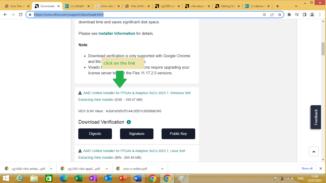
Figure 1.1
Click on the link to download vivado ML for windows system.
After downloading it, you have to install Xilinx_Unified_2023 on your system. To install it ,double click on the setup program as shown in figure 1.2 bellow.
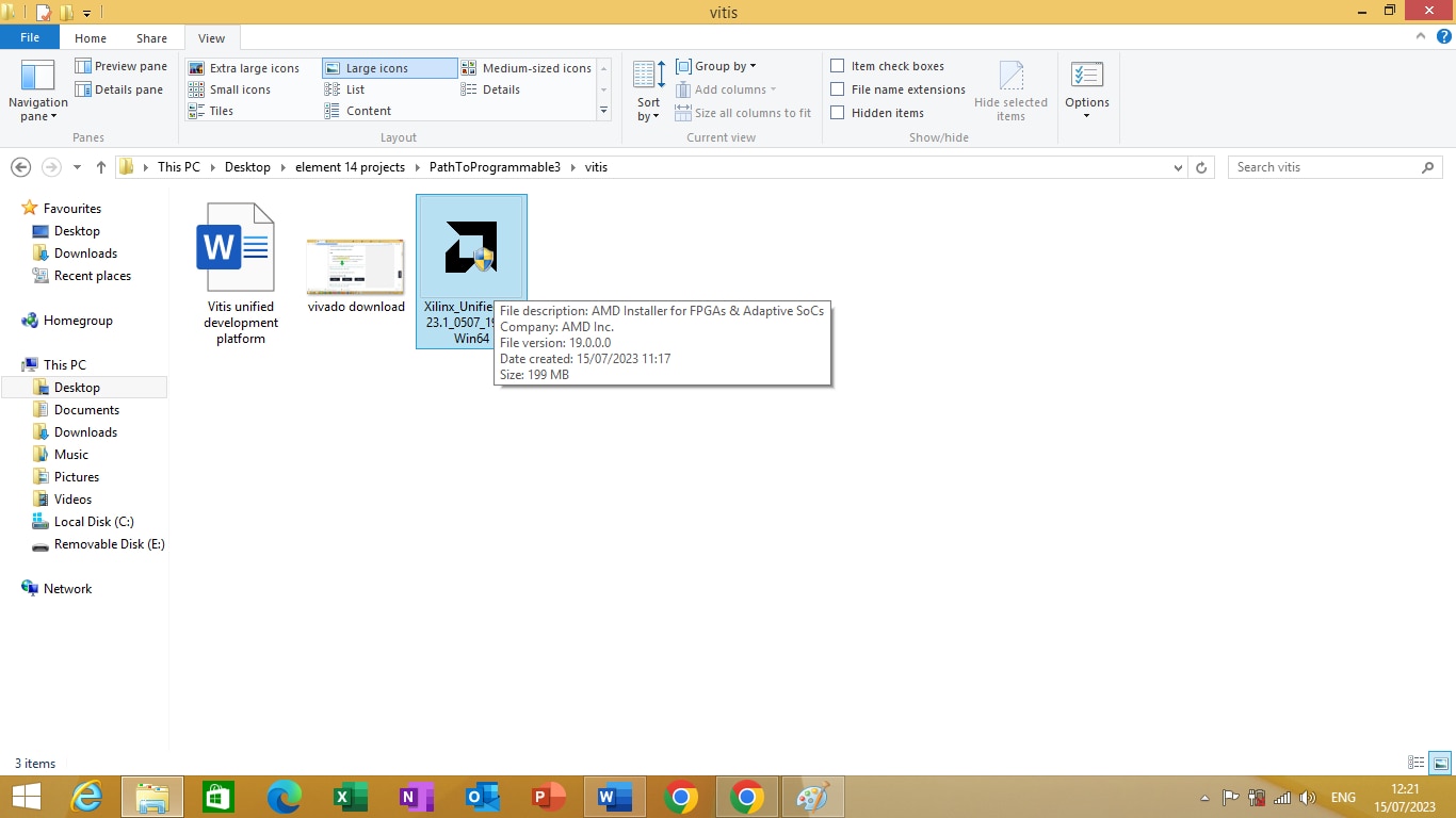
Figure 1.2
After double clicking on it. Setup will start as shown in figure 1.3 bellow
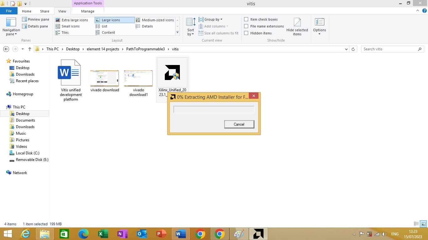
Figure 1.3
Choose Vitis Core development kit installation as shown in figure 1.4 bellow
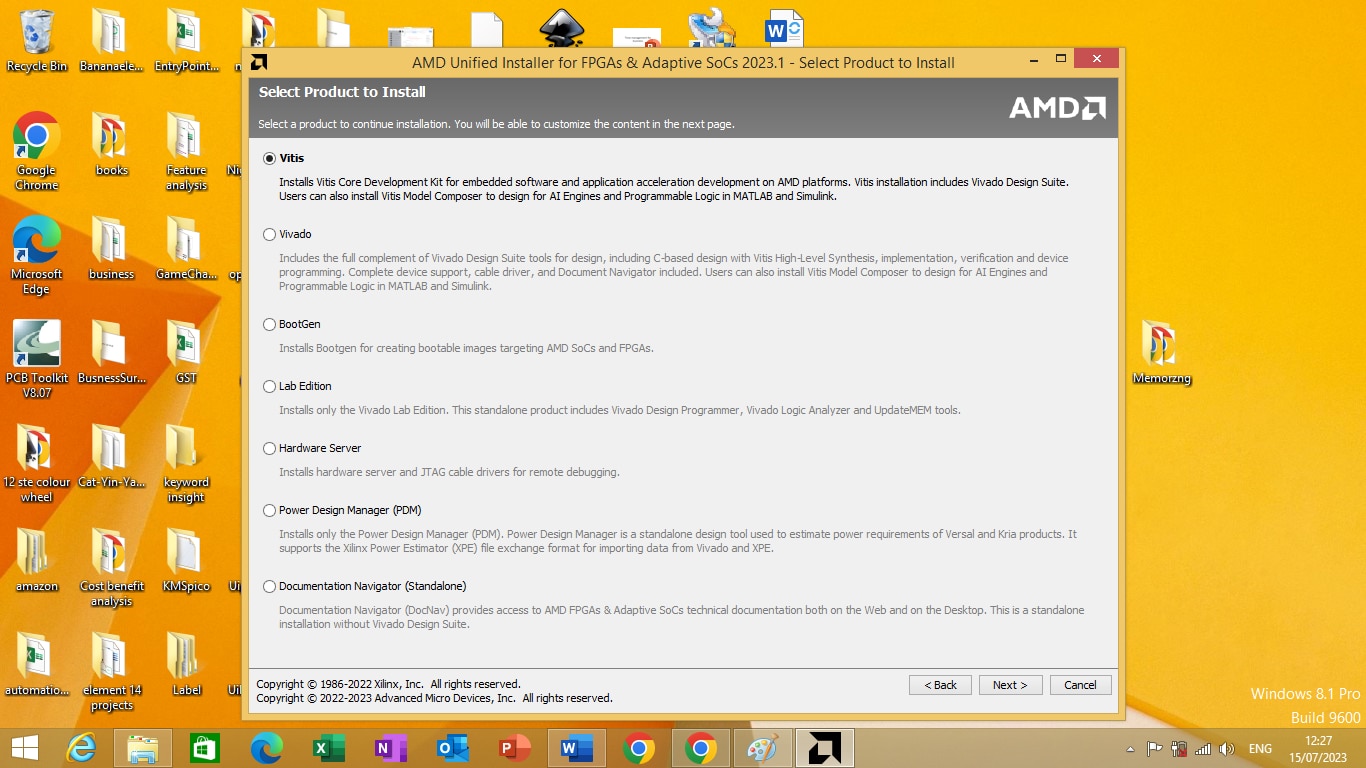
Figure 1.4
After choosing vitis core platform click next. In license and agreement choose all the license as shown in figure 1.5 bellow
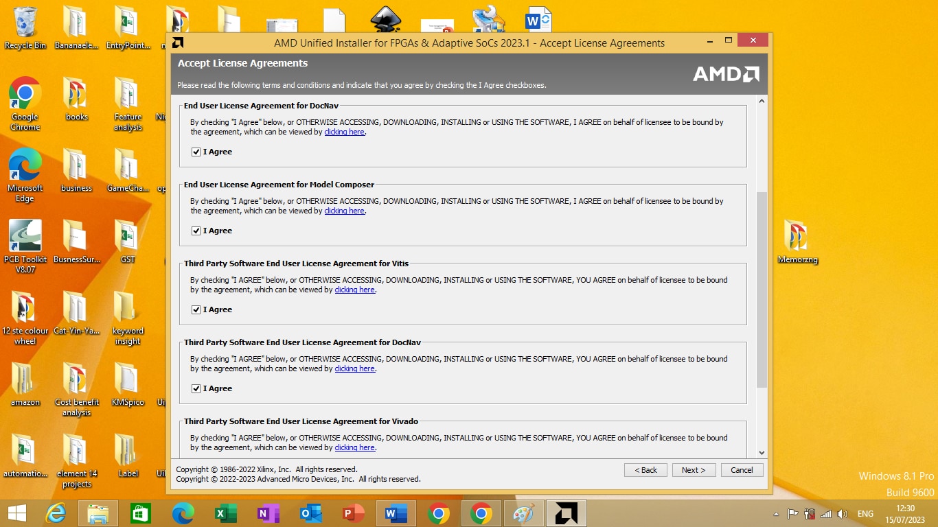
Figure 1.5
After clicking “I Agree” click next to download the vitis core platform and install it.
Understanding USB-to-UART/JTAG Pod
Some questions about serial terminal software
What is a serial port terminal software ?
It is a software that allow you to see data sent to and from your microcontroller
Why do we use serial terminal software ?
We use serial terminal software for troubleshooting/debugging, communication testing, calibrating sensors, configuring modules, and data monitoring.
What is a serial port ?
a serial port is a serial communication interface through which information transfers in or out sequentially one bit at a time.
Some questions about COM port
What is a serial COM port ?
On computers, a serial port is a serial communication interface through which information transfers in or out sequentially one bit at a time.
How does modern integrated circuit implements serial port ?
Modern integrated circuit such as microcontrollers and i/o controller hub of microprocessor implements serial port using either UART or USART
What is an UART ?
A universal asynchronous receiver-transmitter (UART /ˈjuːɑːrt/) is a computer hardware device for asynchronous serial communication in which the data format and transmission speeds are configurable. It sends data bits one by one, from the least significant to the most significant, framed by start and stop bits so that precise timing is handled by the communication channel.
What is a virtual COM port ?
A virtual COM port is a software package emulating a hardware serial port in such a way that your operating system and all applications recognize it and interact with it as though it were a real COM interface.
What is a virtual COM port driver ?
Virtual COM port (VCP) drivers cause the USB device to appear as an additional COM port available to the PC. Application software can access the USB device in the This page contains the VCP drivers currently available for FTDI devices.
Testing USB-to-UART/JTAG Pod
We are going to download and install ‘Hercules serial port’ software for our serial port application. To download the software follow the link given bellow
https://www.hw-group.com/software/hercules-setup-utility
In the above link click on the download button as shown in figure 2.1 bellow
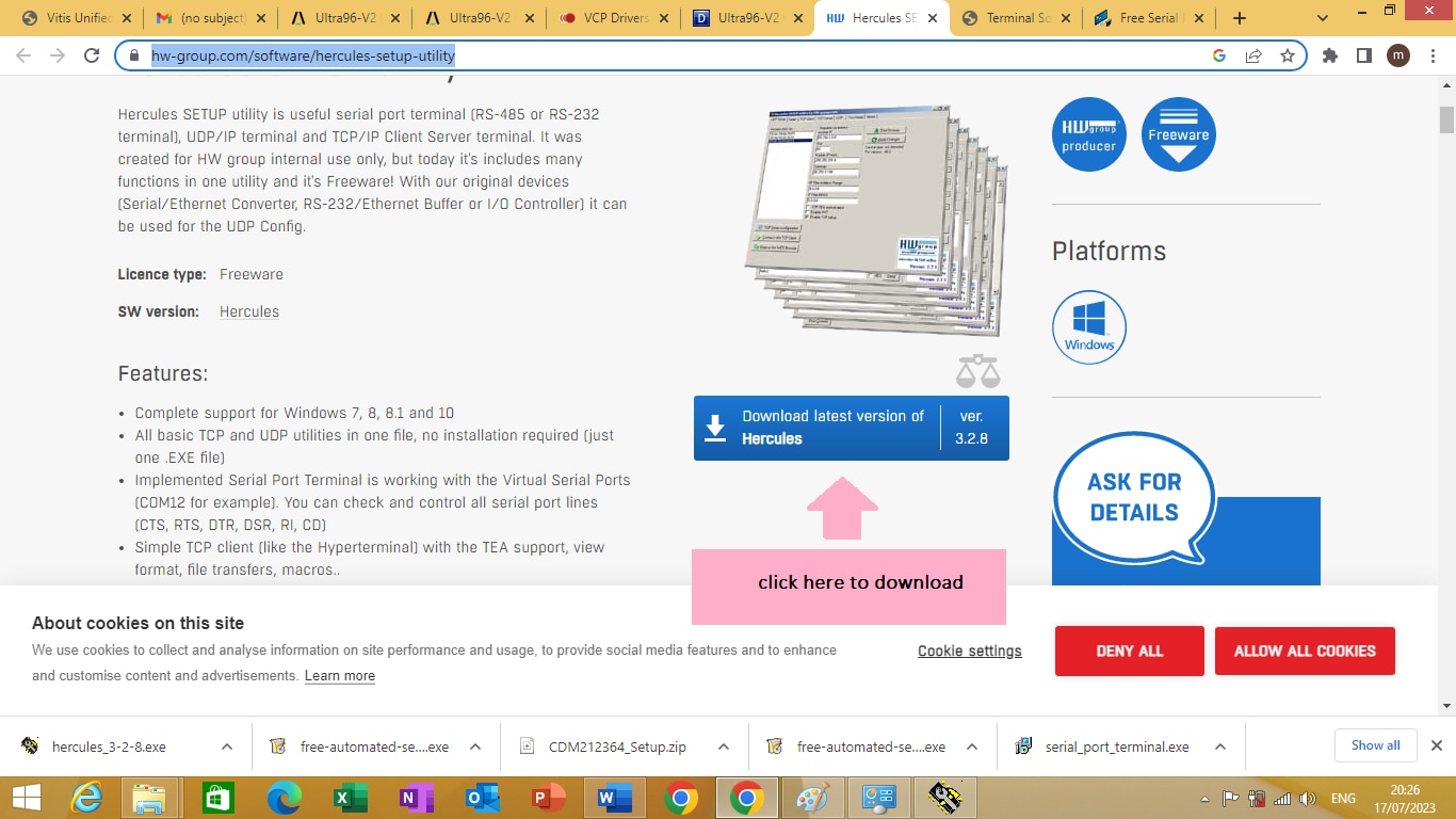
Figure 2.1
After downloading the software you have to install the software. To install the software double click on the ‘hercules_3-2-1’ application as shown in figure 2.2 bellow

Figure 2.2
After double clicking on the setup application software, hercules setup will start as shown in figure 2.3 bellow
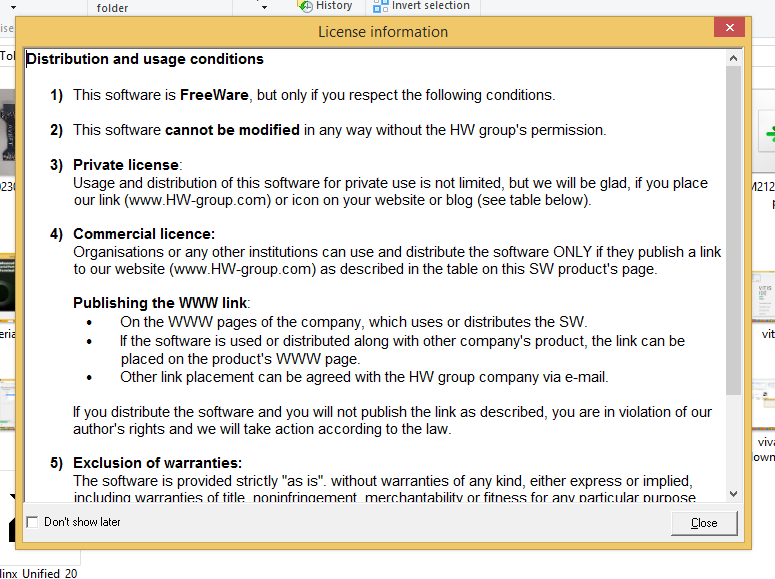
Figure 2.3
Complete the installation by following the instruction given by the setup appropriately.
To run the serial port terminal software click on ‘hercules_3-2-8’ application program as shown in figure 2.4 bellow
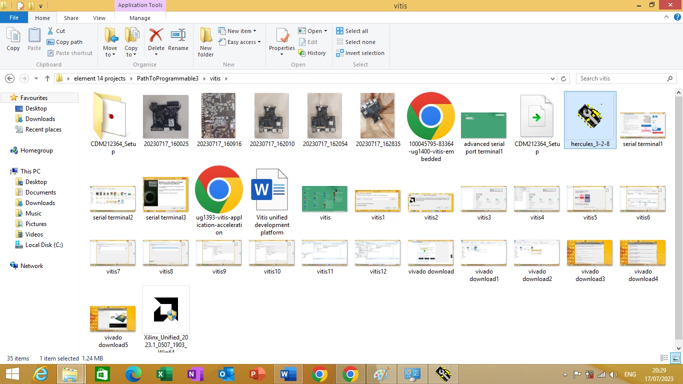
Figure 2.4
After clicking on the application program Hercules application program will start as shown in figure 2.5
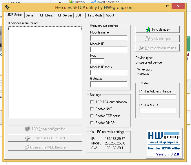
Figure 2.5
Click on serial tab to start the serial port applications as shown in figure 2.6 bellow

Figure 2.6
connect the USB-to-UART/JTAG Pod to the computer via USB cable as shown in figure 2.7 bellow

Figure 2.7
Know you need to figure out the virtual comp port to which your USB to JTAG/UART is connected to.
To know about the COM port no, open device manager from control panel connect the USB to JTAG/UART pod to the USB physical USB port you will see a COM port with number appearing on device manager as shown in figure 2.8 bellow
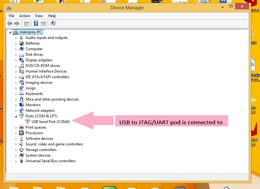
Figure 2.8
Know we can test weather the USB to JTAG/UART pod is working properly or not. In serial tab in name mention COM4 as shown in figure 2.9 bellow and click open button on the screen. You will get serial port com4 open Received/send data window

Figure 2.9
Vitis IDE project execution
There are 5 steps involved for creating a project in Vitis IDE
- Create workspace
- Create Platform
- Modifying BSP
- Create Application Project
- Deploying Hardware
Launching the Vitis IDE
In this section we are going to create a sample application name hello world using Vitis IDE. To start creating application you have to first Launch the vitis software platform as shown in figure 3.1 bellow.
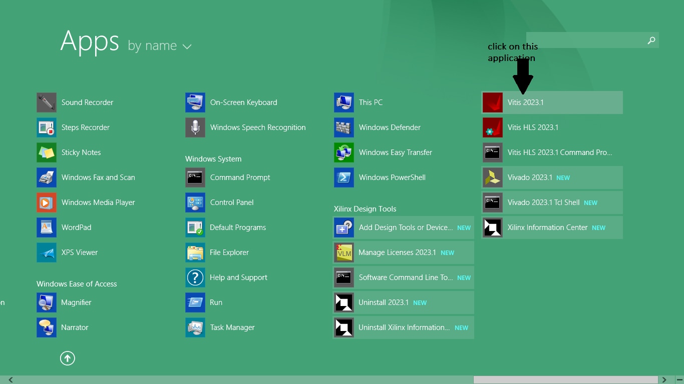
Figure 3.1
After clicking on ‘vitis 2023.1’ a dialog box will open as shown in figure 3.2 bellow on it you need to create a workspace and than click on launch button.
To create workspace edit the workspace name on 'C:\Users\manojroy\workspace' to the name you wish. We will edit it's name to 'C:\Users\manojroy\workspace2'
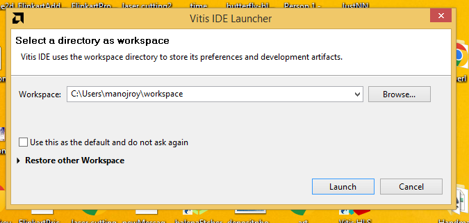
Figure 3.2
The following IDE will be displayed as shown on figure 3.3 bellow
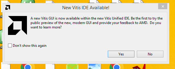
Figure 3.3
Click on No button to start the Vitis IDE. The vitis IDE can be seen in figure 3.4 bellow
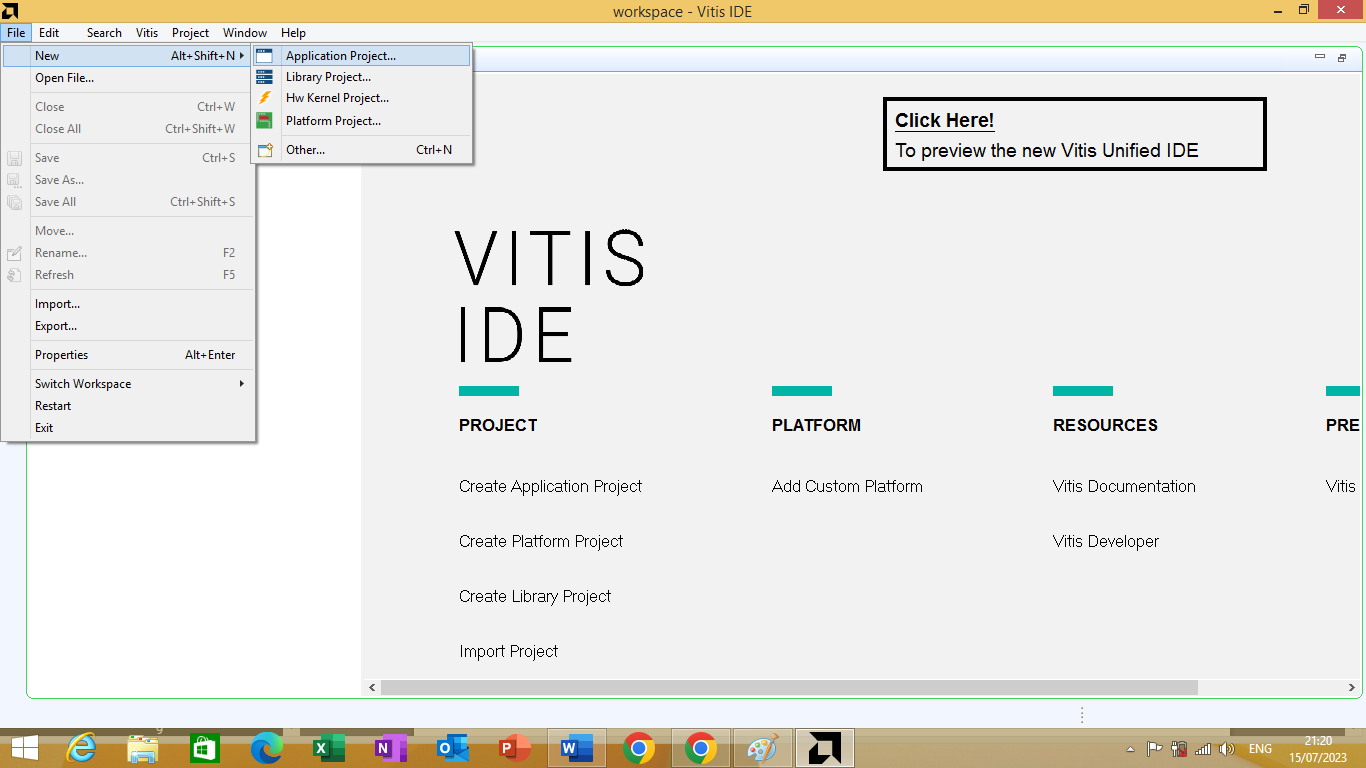
Figure 3.4
Platform Project
Know we will create platform project. As this is the second step in creating application using Vitis Platform. To create platform project Click File -> New -> Platform Project
As shown in figure 3.5 bellow
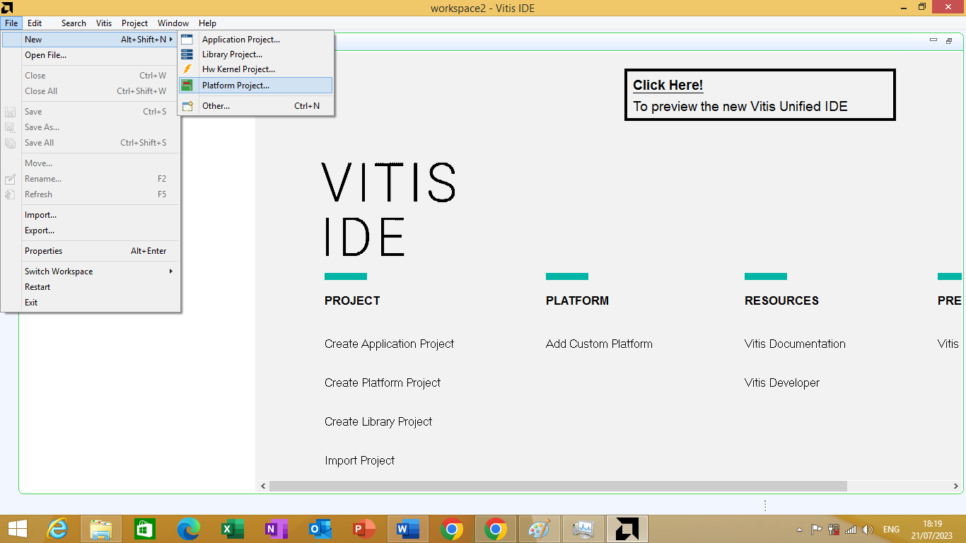
Figure 3.5
After clicking on it 'create a new platform project' window will open as shown in figure 3.6 bellow on it mention the desired platform name as you wish. We will mention platform name is 'NewUltra96-v2' than we will click next.
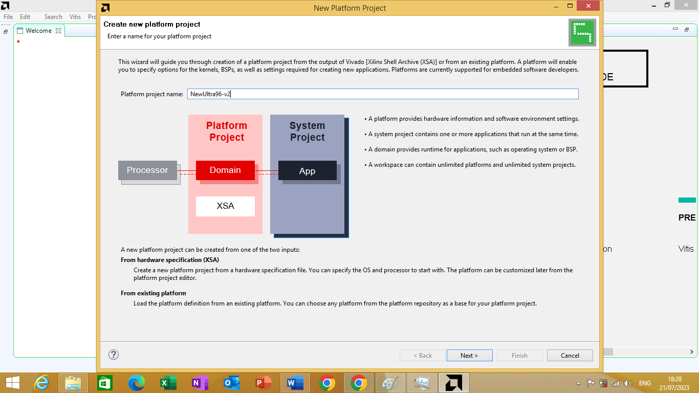
figure 3.6
A platform window will open. In it we are going to use our own custom platform we have created. We will click on "Created a new platform from hardware (XSA)" option. As shown in figure 3.7 bellow.
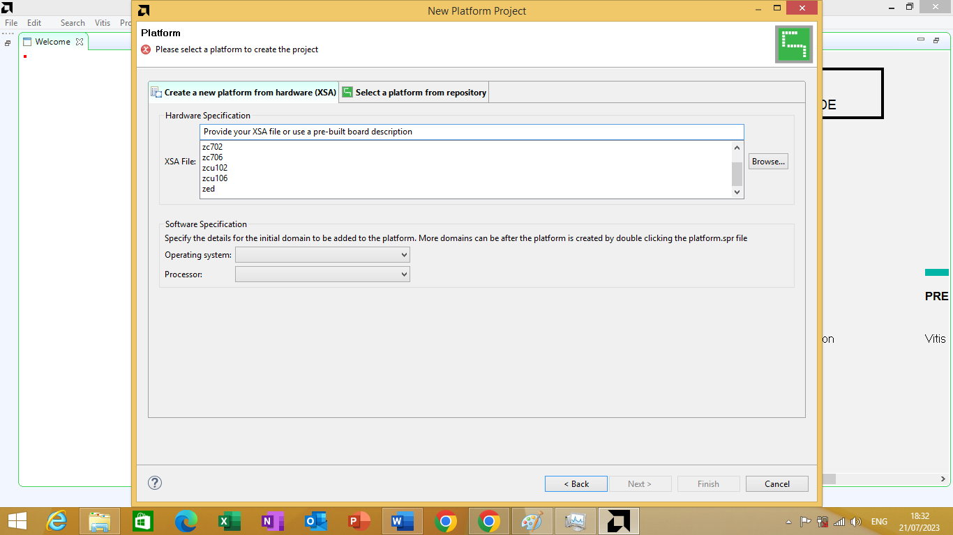
Figure 3.7
Click Browse to locate and select the .xsa file we have exported from Vivado as shown in figure 3.8 bellow
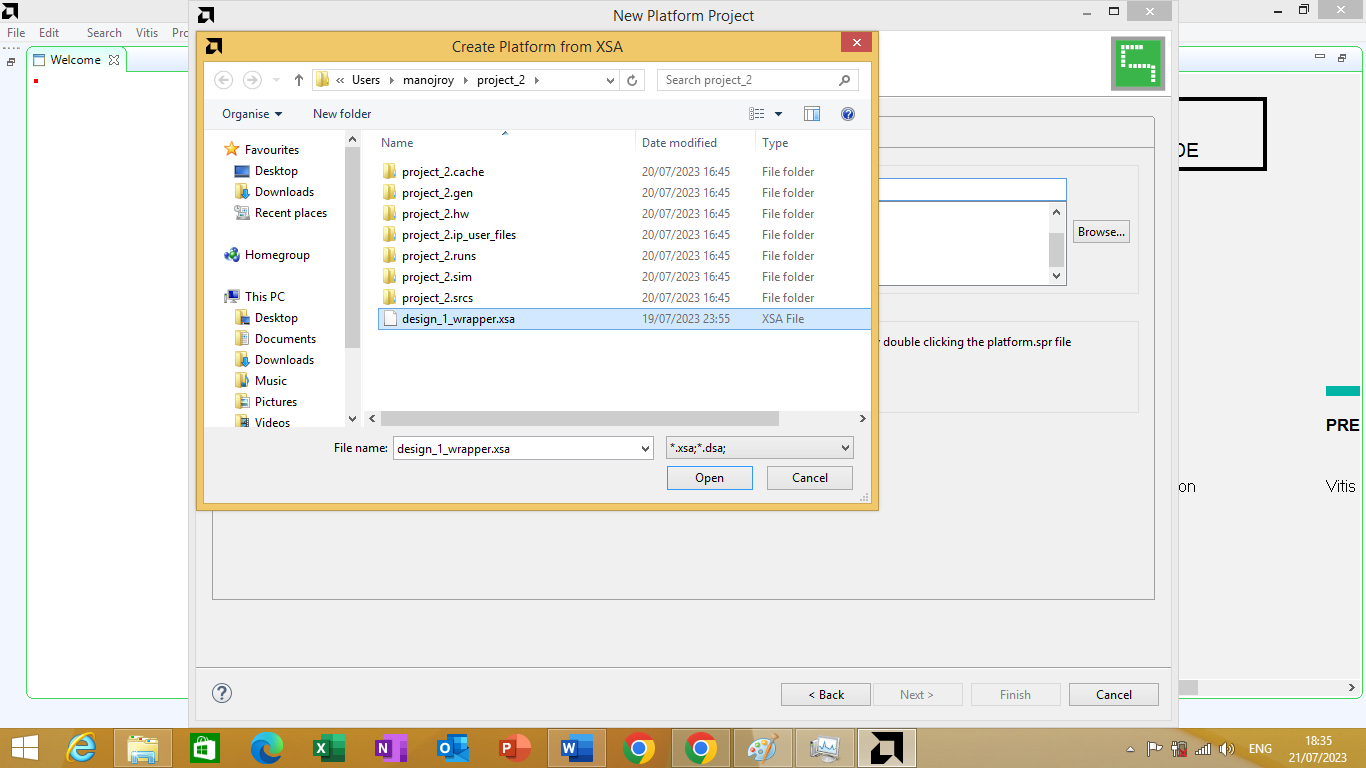
Figure 3.8
Our hardware platform project is known as 'design_1_wrapper.xsa'. After clicking on it, we will click open. it will appear in the list along with the previously populate generic platforms. As shown in figure 3.9 bellow.
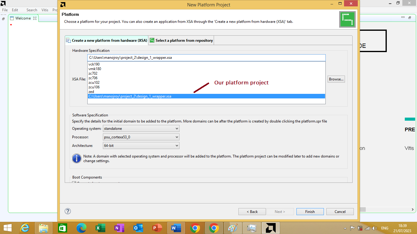
Figure 3.9
we will click on finish button to open the custom platform on vitis IDE as shown in Figure 3.10 bellow
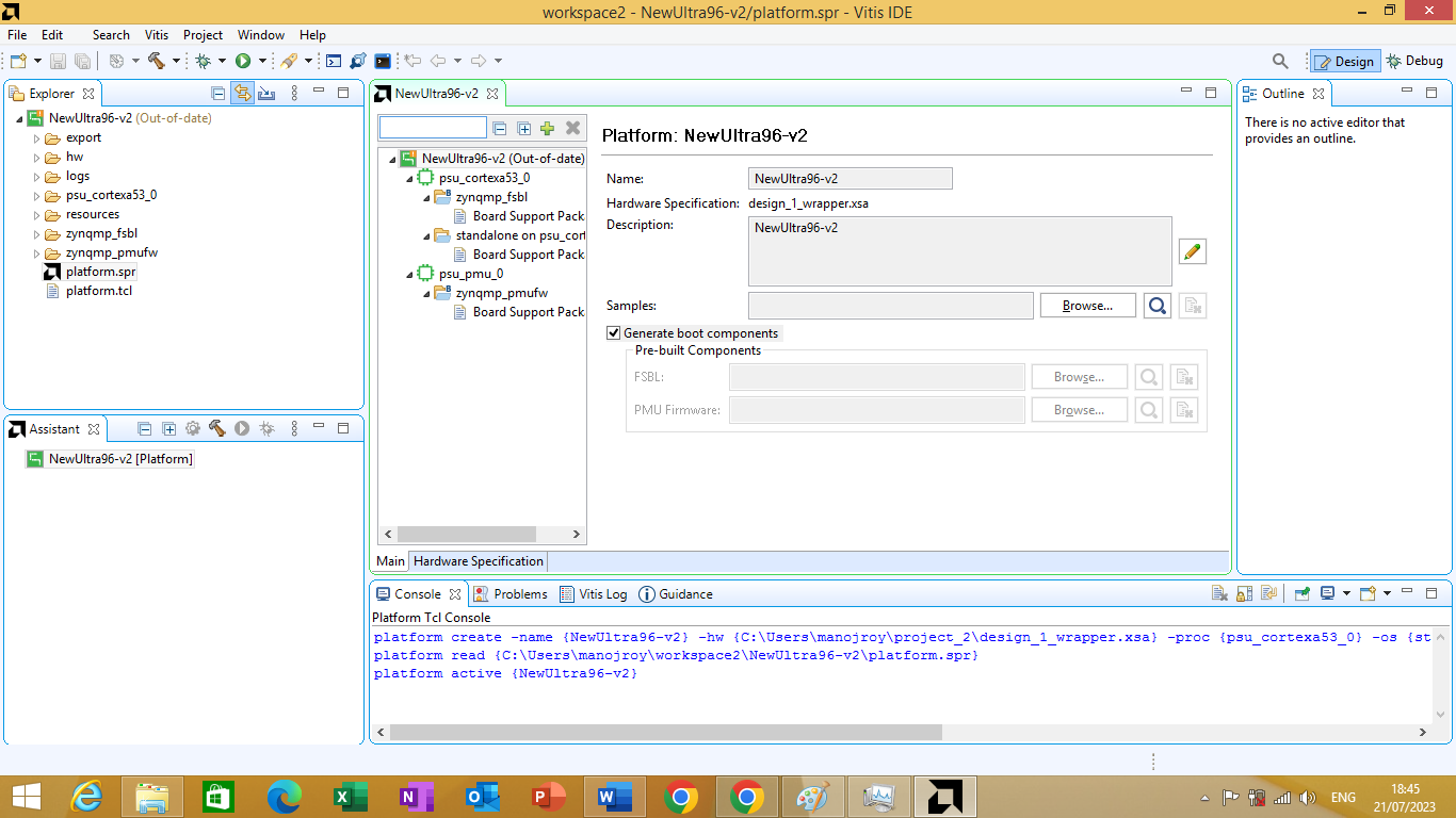
Figure 3.10
Modifying BSP
By default the BSP (board support package) uses UART0 for the standard input and outputs (known as "stdin" and "stdout"). These are the devices used by our application that we have created for Cortex A53 processor to send or receive data from the console. From the Ultra96v2 schematics and Zynq MPSoC settings in Vivado we can verify that it's the UART1 that is actually connected to the JTAG UART on the Ultra96v2 board. So we need to update this in our BSP.
To do this click on board support packages as shown in figure 3.11 bellow
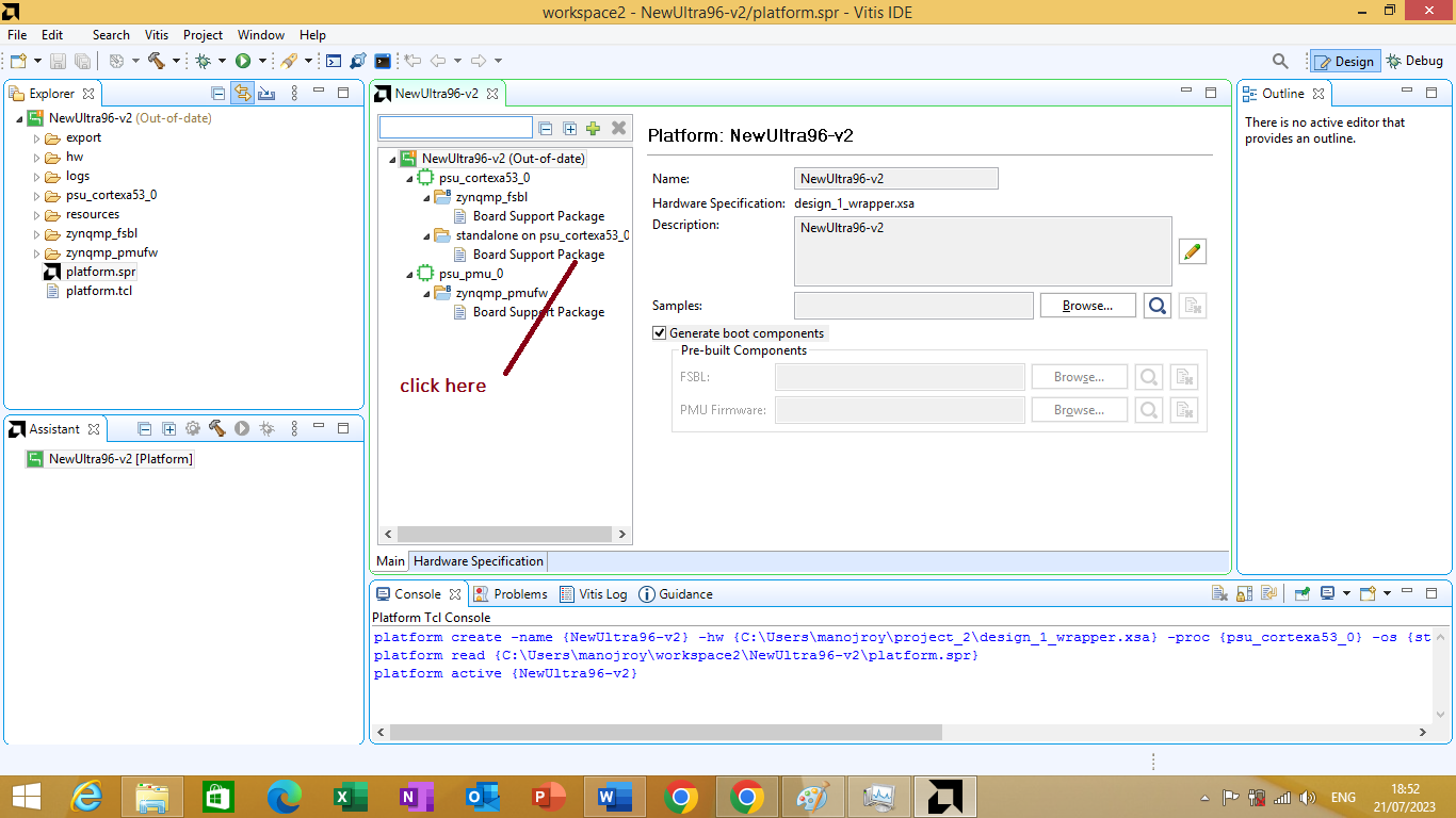
Figure 3.11
After clicking on it board support package window will open as shown in figure 3.12 bellow
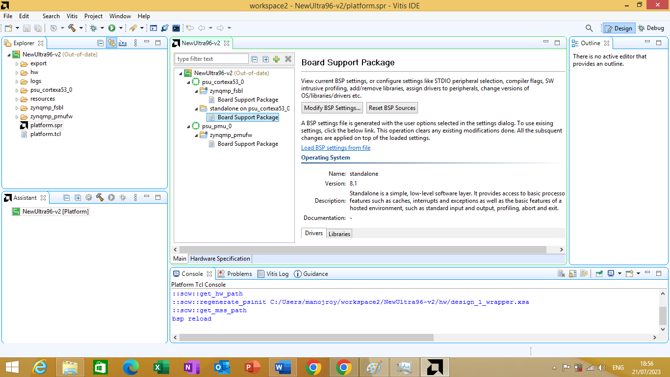
Figure 3.12
On it click on 'Modify BSP Settings' button. After clicking on it 'Board Support Package Settings' window will open as shown in figure 3.13 bellow
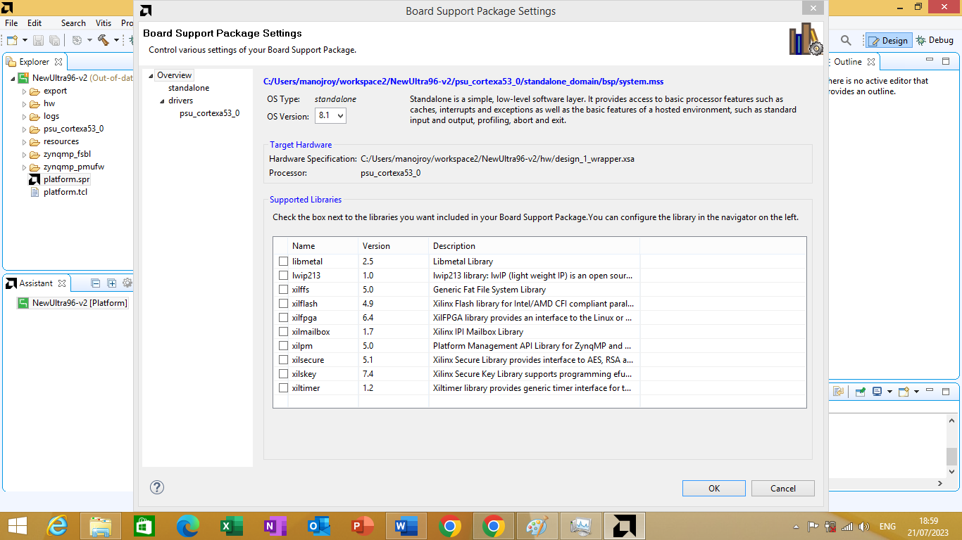
Figure 3.13
On the left side , click "standalone" category as shown in figure 3.14 bellow
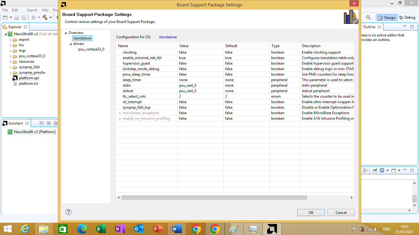
Figure 3.14
Now you can see the stdin and stdout parameters, which are both set to psu_uart_0 currently. change both of them to psu_uart_1. As shown in figure 3.15 bellow

Figure 3.15
And then click Ok. we can observe that out Platform project is showing to be "out-of-date". As shown in Figure 3.16 bellow
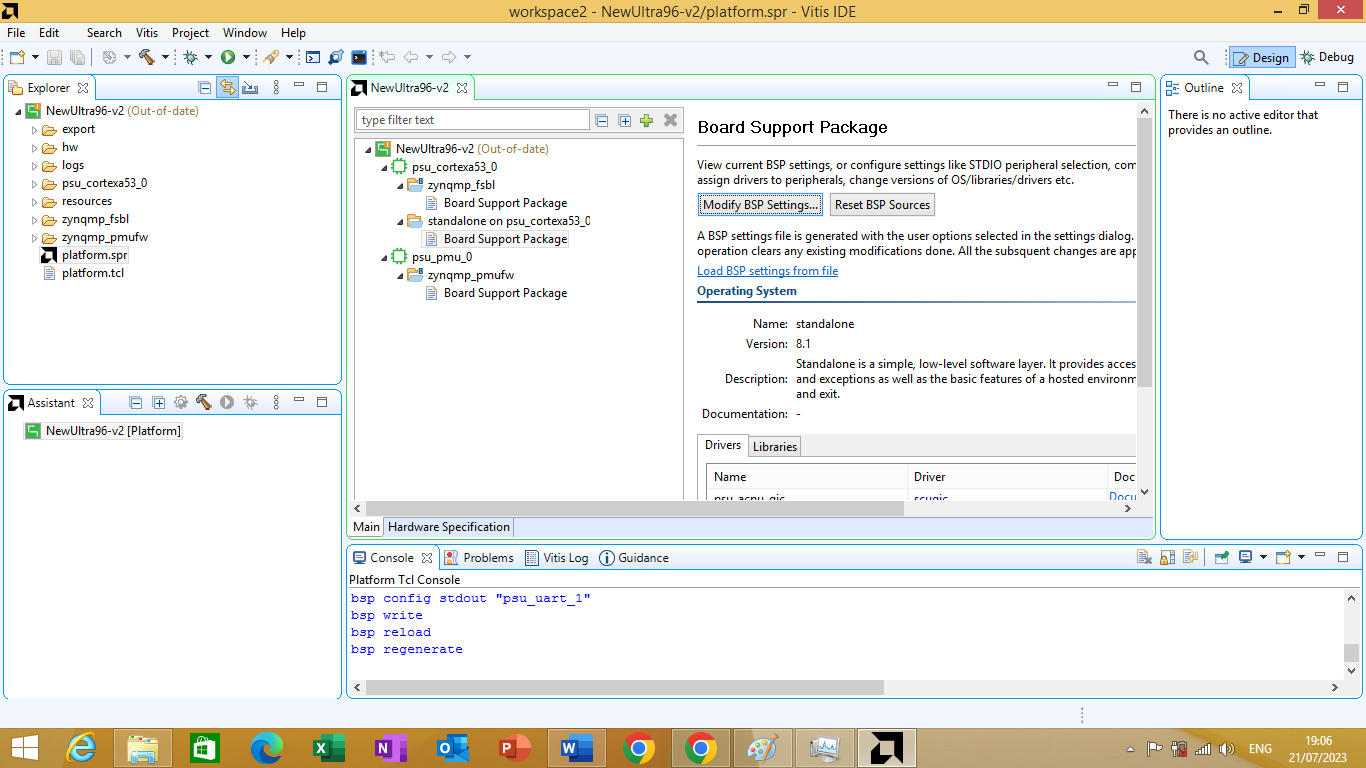
Figure 3.16
To fix it, we right click the platform project name, and click "Build Project". As shown in figure 3.17 bellow
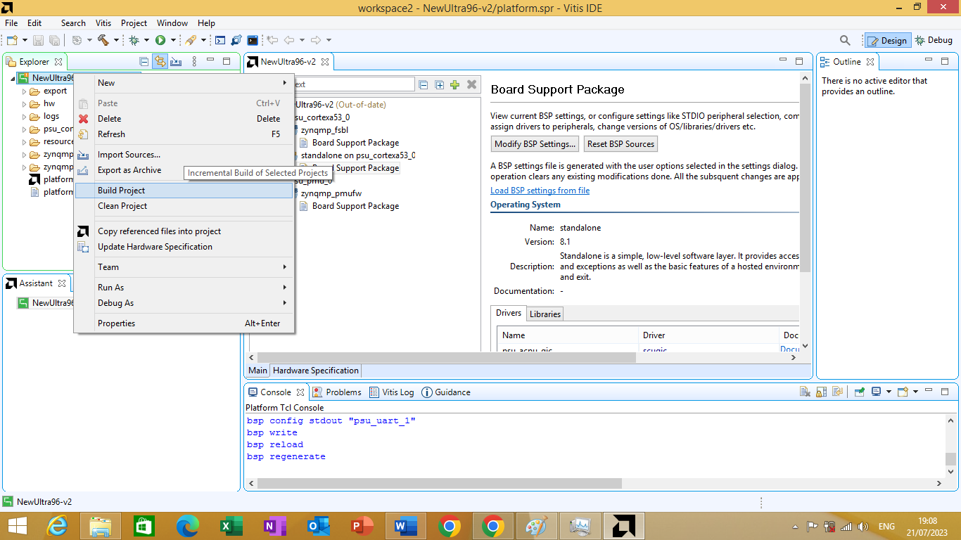
Figure 3.17
After the project is build you will no longer see 'out-of-date' anymore.
Application Project
Since the platform from project is created know we can build application project. In the Main Vitis window, click File -> New -> New Application Project. As shown in figure 3.18 bellow
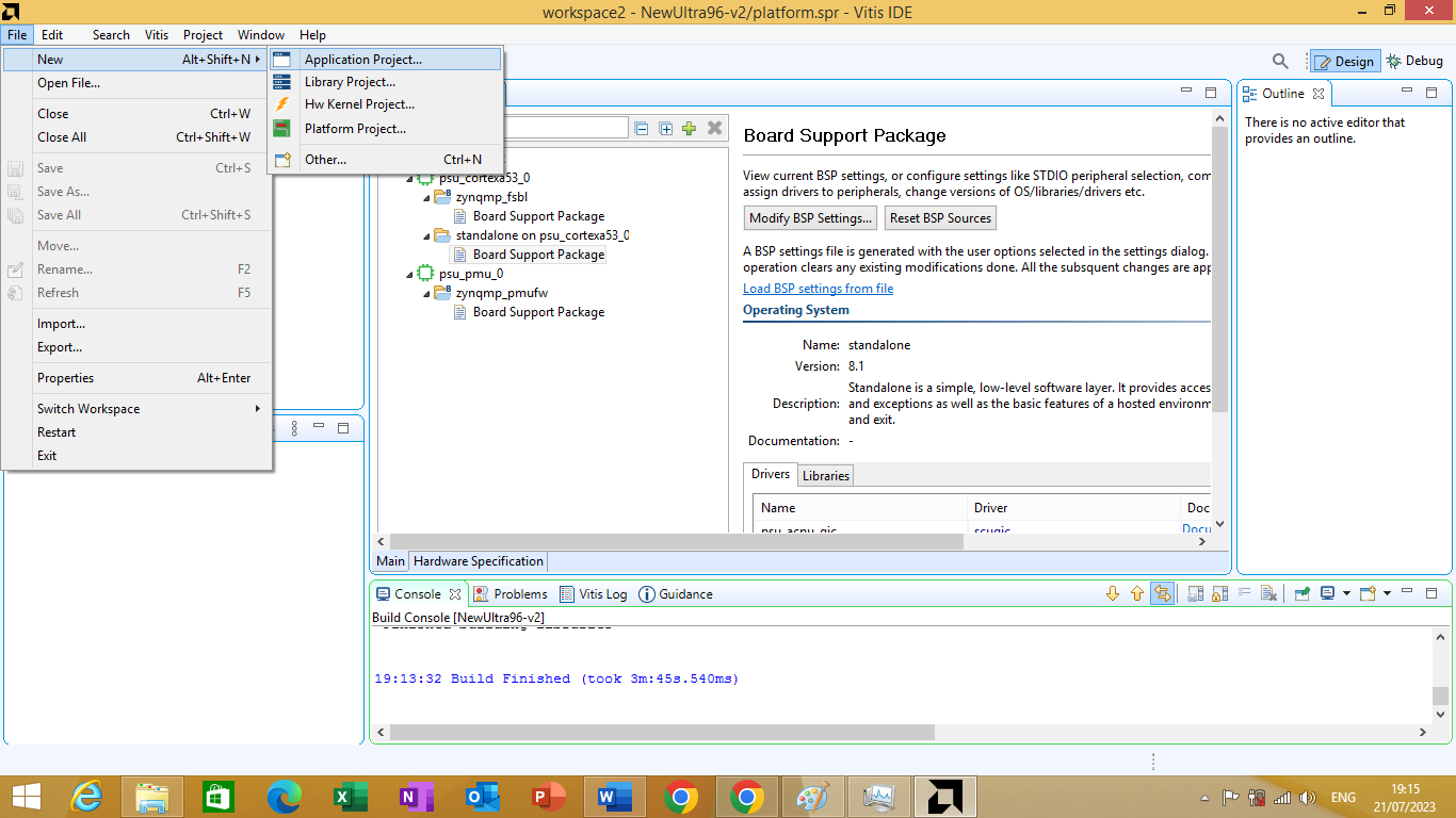
Figure 3.18
This opens a window to create a new application project as shown in figure 3.19 bellow.
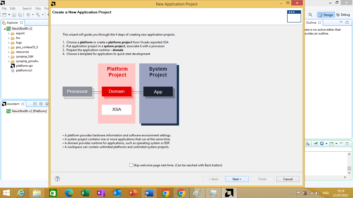
Figure 3.19
click next a platform window will open to select the desired platform. We will select the custom platform that we have created for ultra96v2 board as shown in figure 3.20 bellow
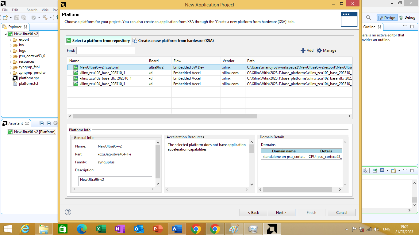
Figure 3.20
After clicking next an Application Project Details window will open. On the application project name text box we will mention the project name we desired as shown in figure 3.21 bellow
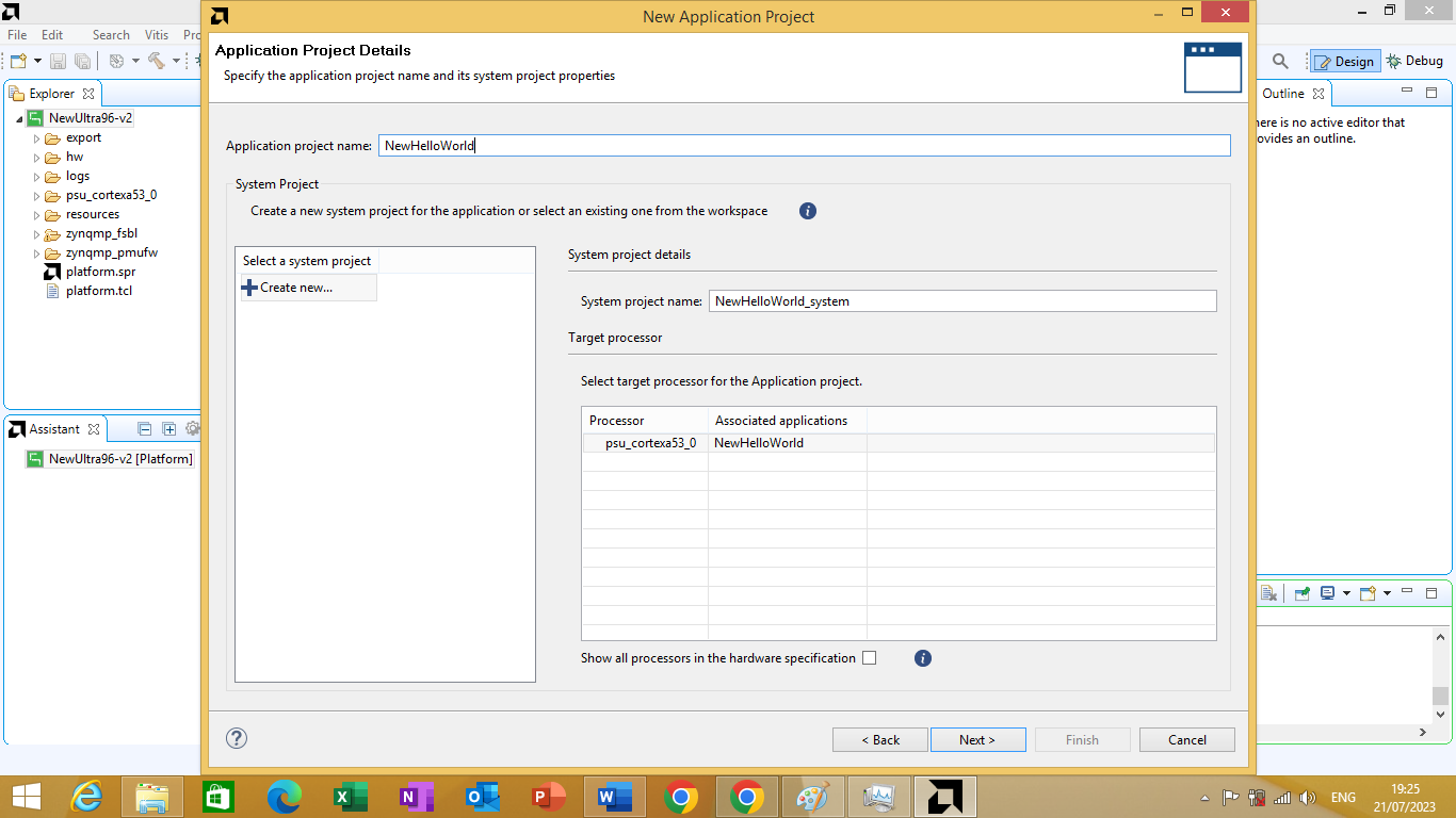
Figure 3.21
After clicking next a domain window will open the is no changes that needs to be made in domain window. We will click next A template window will open we will choose 'Hello World' template as shown in figure 3.22 bellow.
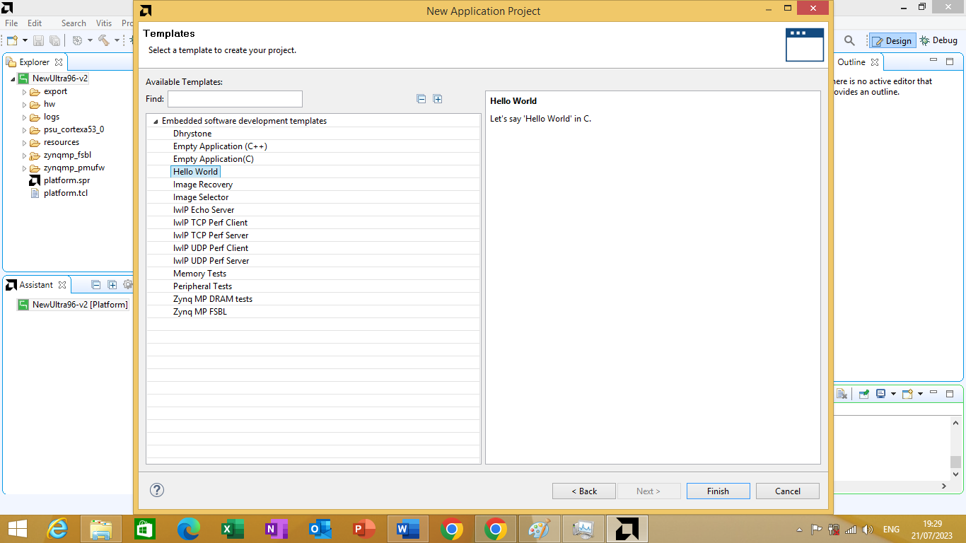
Figure 3.22
we will click finish after choosing the hello world template. You can see the new Application project appear in the "Explorer" window on the left side. As shown in figure 3.23 bellow
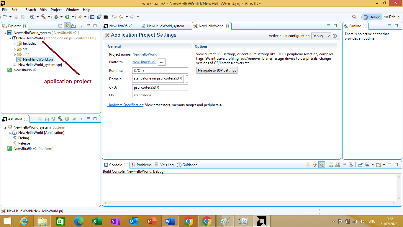
Figure 3.23
To build the Application, first make sure we have the Application Project selected at top level then click Project -> Build Project as shown in figure 3.24 bellow
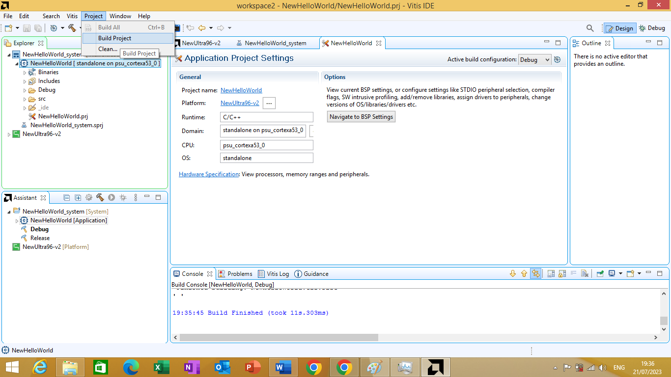
Figure 3.24
Deploying on hardware
Now Since our application is compiled, we can launch it on Ultra96v2 board.
Before launching it on hardware we need to setup our hardware first to do so follow the steps given bellow
- Connect JTAG Adapter Pod to the Ultra96v2. Make sure the pins' alignment is good before you push the two boards together.
- On the Ultra96v2, make sure SW3 is set to [ON, ON] positions (both switches in ON position) to set boot mode to JTAG.
- Apply power to the board using the correct power supply plugged into the board's barrel jack.
- Connect a USB cable from the JTAG Adapter pod's USB port to the development computer's USB port.
- Press the power switch (SW4) to turn on the board
Now, we can launch the application in Debug mode by right clicking our application's name in Explorer window -> Debug As -> Launch Hardware. As shown in figure 3.25 bellow.
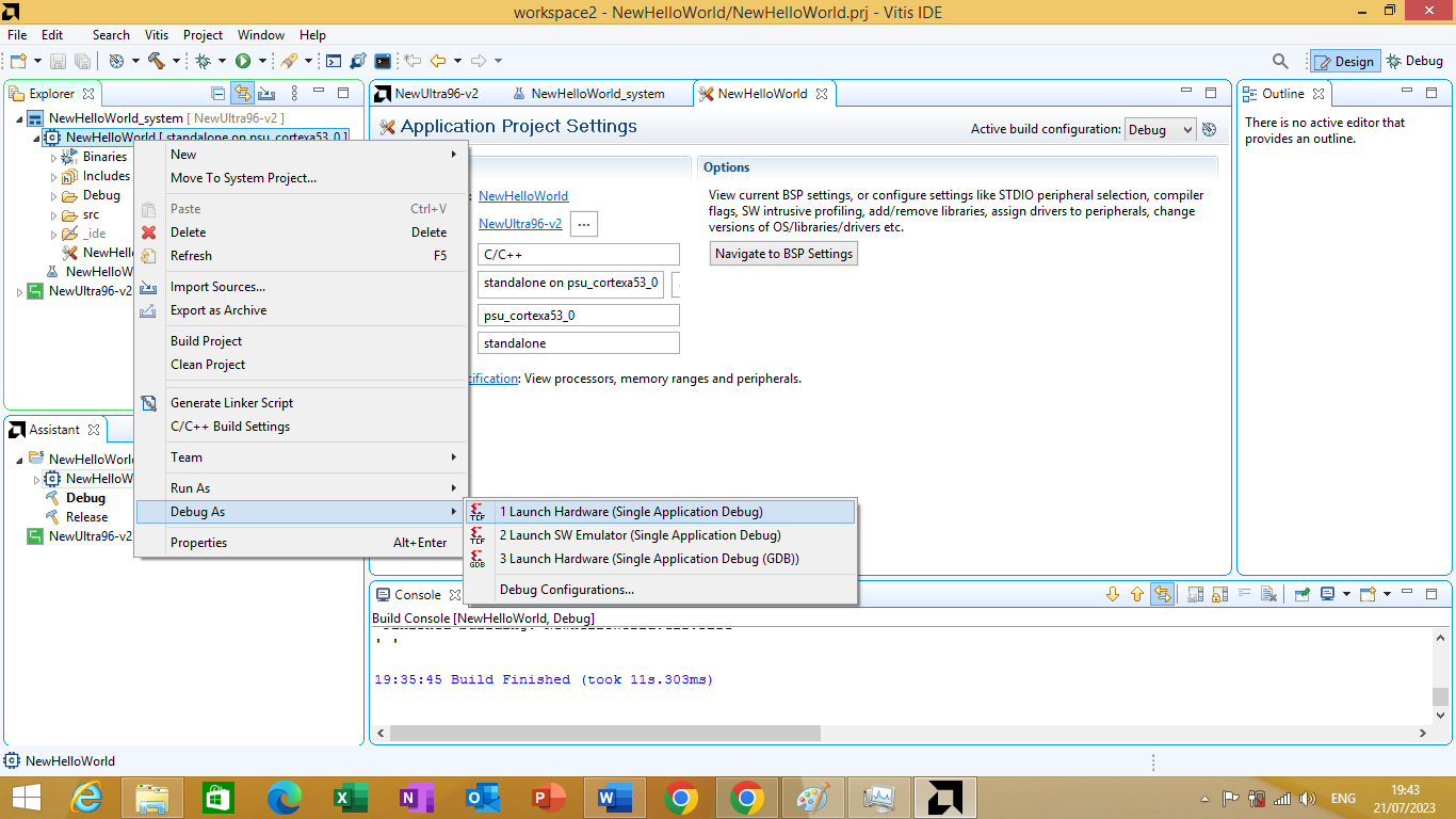
Figure 3.25
After launching the application on hardware. we will test the application. To test the application you need to click on 'Vitis Serial Terminal' window as shown in figure 3.26 bellow
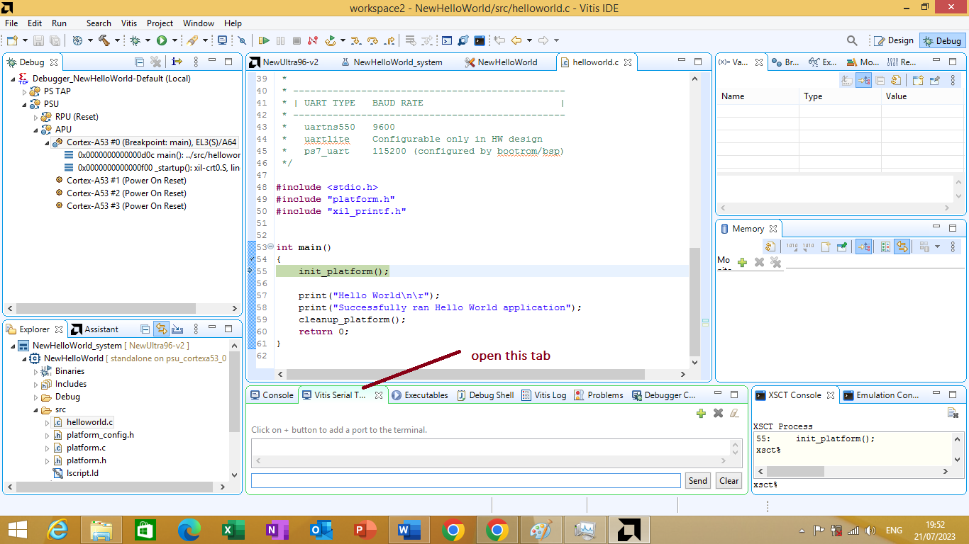
Figure 3.26
On it click on + sign to open serial terminal setting as shown in figure 3.27 bellow.

Figure 3.27
After clicking on it Serial terminal port setting window will open as shown in Figure 3.28 bellow. On it set port as Com4, Data bit 8, Stop bit 1, parity none, flow control none than press on
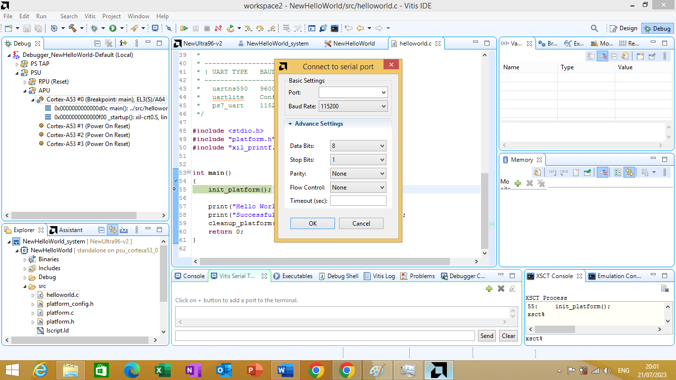
Figure 3.28
After clicking ok The Vitis Serial Console should display a message "Connected to COM4 at 115200" as shown in figure 3.29 bellow
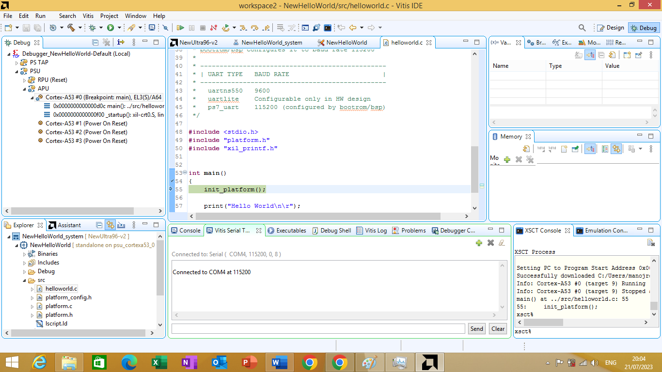
Figure 3.29
Now, you can proceed with executing the application by clicking on Run -> Resume in the Vitis window. As shown in figure 3.30 bellow
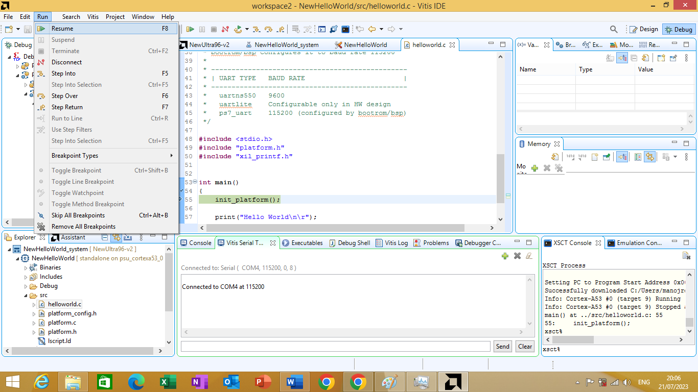
Figure 3.30
After resuming the application we will se our message in Vitis Serial terminal window as shown in figure 3.31 bellow
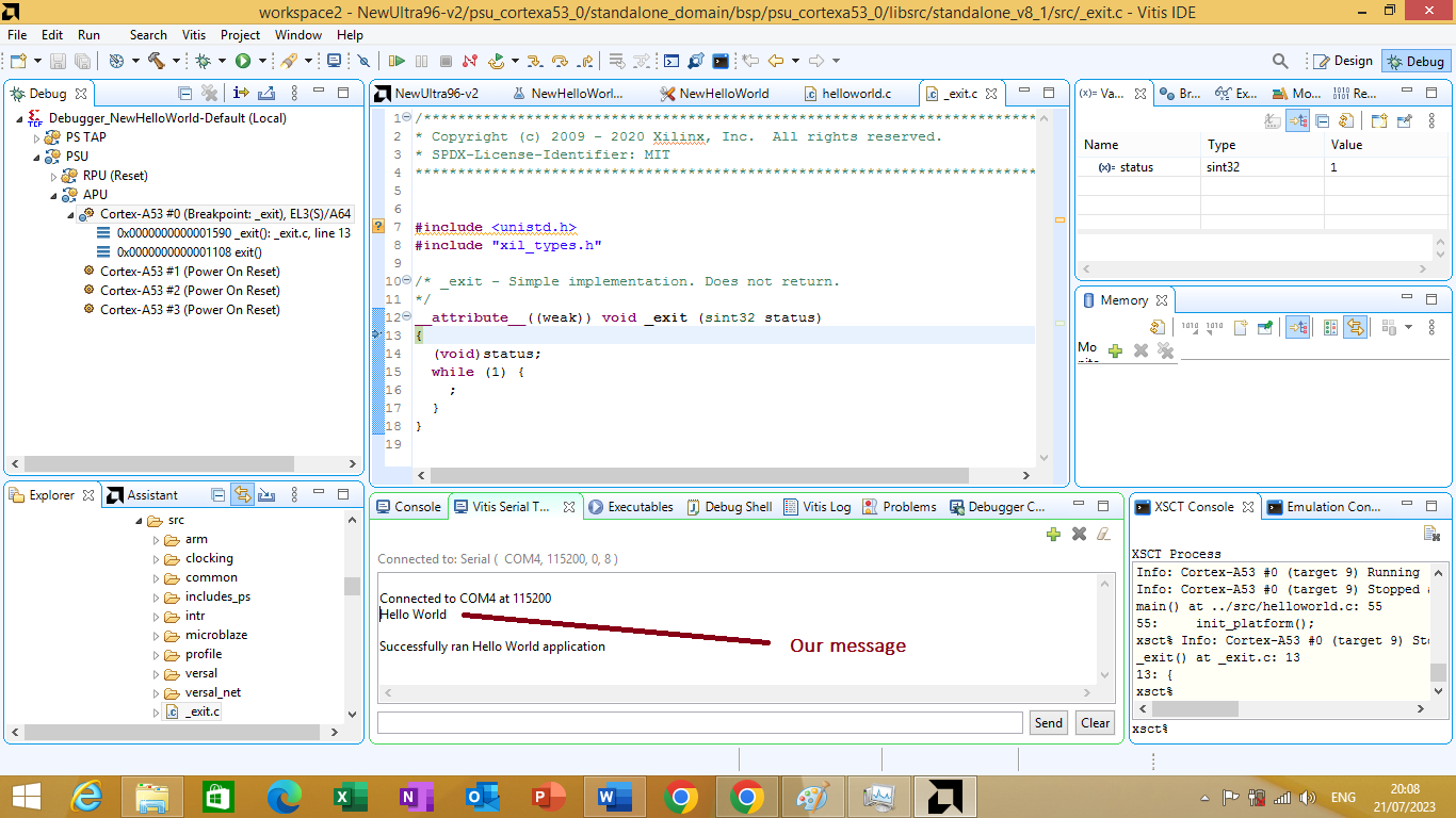
Figure 3.31