


Table of Contents
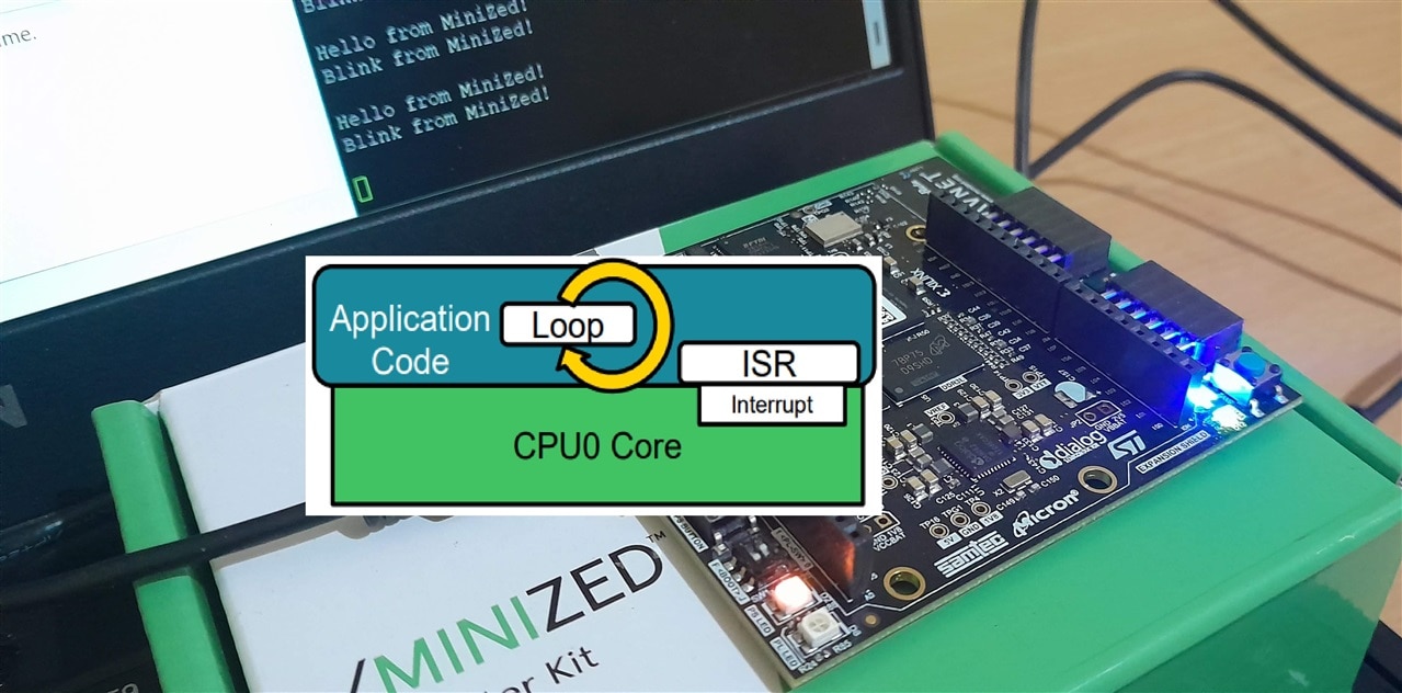
Flowing through the MiniZed tutorial track (+) MiniZed Software Technical Training 2021.1- element14 Community, I hit across the interrupts section. This quite caught my interest and thought of exploring further and building some instances. Real-time computing often requires interrupts to respond quickly to events and the ZYNQ SoC offers both hardware and software interrupts which we'll explore with examples further.
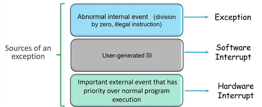
Enough saying interrupt! What's it actually?
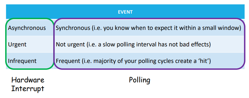
Interrupts are a type of exception for the processor which tries to gain its attention out of the routine task it is continuously running. The processor has the privilege to always prioritizing the interrupt based on its type and as defined by the user. Another way around is for the processor to continuously check by itself at a regular interval if there are any occurrences of an exception in the system. This is polling and is probably used if the system can't control its rush!
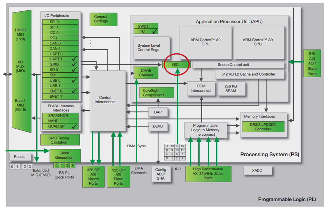
The Zynq SoC uses a Generic Interrupt Controller (GIC) to process interrupts. The GIC handles interrupts from the following sources:
- Software-generated interrupts – There are 16 such interrupts for each processor. They can interrupt one or both of the Zynq SoC’s ARM® Cortex-A9 processor cores.
- Shared peripheral interrupts – Numbering 60 in total, these interrupts can come from the I/O peripherals, or to and from the programmable logic (PL) side of the device.
- Private peripheral interrupts – The five interrupts in this category are private to each CPU—for example CPU timer, CPU watchdog timer and dedicated PL-to-CPU interrupt #.
# This is an interesting blog by Jan Cumps on Zynq PS-PL interrupt (+) Learning Xilinx Zynq: Interrupt ARM from FPGA fabric - element14 Community
When an interrupt occurs within the Zynq SoC, the processor will take the following actions:
- The interrupt is shown as pending.
- The processor stops executing the current thread.
- The processor saves the state of the thread in the stack to allow processing to continue once it has handled the interrupt.
- The processor executes the interrupt service routine, which defines how the interrupt is to be handled.
- The processor resumes the operation of the interrupted thread after restoring it from the stack.
Hardware and Software handled interrupt
Hardware interrupts are generated by external devices that are connected to the microprocessor through pins or buses. When a device needs the attention of the microprocessor, it sends a signal to a specific interrupt line, which is assigned a priority level. The microprocessor then saves its current state and jumps to the corresponding interrupt handler. Hardware interrupts are useful for handling asynchronous events, such as user input, data transfer, or device status changes. They allow the microprocessor to respond quickly and efficiently to external stimuli, without wasting cycles on polling or waiting.
Software interrupts are generated by the microprocessor itself, as a result of executing certain instructions or encountering certain conditions. They allow the microprocessor to interact with the software environment, and to handle different situations gracefully and consistently.
The choice between what to choose isn't quite straightforward but depends on what is the sensitivity of the interrupt. Hardware interrupts can be preferred when the software running is time and complexity critical and have no luxury to scan peripherals for an event. It is just like there is a code running and doing its own job and gives all interrupt control to the peripheral hardware itself. All the systems may not have this hardware interrupt feature built-in though.
Writing some Code
The BSP contains a number of functions that greatly ease this task of creating an interrupt-driven system. They are provided within the following header files:
- Xparameters.h – This file contains the processor’s address space and the device IDs.
- Xscugic.h – This file holds the drivers for the configuration and use of the GIC.
- Xil_exception.h – This file contains exception functions for the Cortex-A9
Hardware Interrupt
This code uses the interrupt capability of the GPIO to detect the push button events and set the output LEDs based on the input and also hardware interrupt based on edge detection. An Interrupt is generated whenever the PS Push Button is pressed by using Raising Edge Triggered Interrupt on that Input Pin '0' where it is connected.
The interrupt system is set up by the following code for GPIOs and also the processor is told:
	/*
	 * Connect the interrupt controller interrupt handler to the hardware
	 * interrupt handling logic in the processor.
	 */
	Xil_ExceptionRegisterHandler(XIL_EXCEPTION_ID_INT,
				(Xil_ExceptionHandler)XScuGic_InterruptHandler,
				GicInstancePtr);

	/*
	 * Connect the device driver handler that will be called when an
	 * interrupt for the device occurs, the handler defined above performs
	 * the specific interrupt processing for the device.
	 */
	Status = XScuGic_Connect(GicInstancePtr, GpioIntrId,
				(Xil_ExceptionHandler)XGpioPs_IntrHandler,
				(void *)Gpio);
	if (Status != XST_SUCCESS) {
		return Status;
	}

	/* Enable Level edge interrupts for all the pins in bank 0 Except Pin "0" where Push Button is Connected.
		For Pin '0' We set Raising Edge Triggered Interrupt		*/
	XGpioPs_SetIntrType(Gpio, GPIO_BANK, 0x01, 0xFFFFFFFF, XGPIOPS_IRQ_TYPE_EDGE_RISING);

	/* Set the handler for gpio interrupts. */
	XGpioPs_SetCallbackHandler(Gpio, (void *)Gpio, IntrHandler);


	/* Enable the GPIO interrupts of Bank 0. */
	XGpioPs_IntrEnable(Gpio, GPIO_BANK, (1 << Input_Pin));


	/* Enable the interrupt for the GPIO device. */
	XScuGic_Enable(GicInstancePtr, GpioIntrId);


	/* Enable interrupts in the Processor. */
	Xil_ExceptionEnableMask(XIL_EXCEPTION_IRQ);
Service routine controls what to do when the interrupt event comes up:
/* This function is the user layer callback function for the bank 0 interrupts of
* the GPIO device. It is the servie routine when the interrupt occurs - truns ON
* the onboard RED LED for 1 second*/

static void IntrHandler(void *CallBackRef, u32 Bank, u32 Status)
{
	XGpioPs_WritePin(&Gpio, Output_Pin_R, 0x1);

	/* EDIT: for avoiding sleep() inside ISR line 11 moved to the begining of main loop*/
	//sleep(1);
	//XGpioPs_WritePin(&Gpio, Output_Pin_R, 0x0);

	xil_printf("Successfully cleared the interrupt\n\n\r");     /*serial terminal write*/
}
In this hardware interrupt case, the is no shared variable or a software flag that holds interrupt status. The ISR function is the user layer callback function for the bank 0 interrupts of the GPIO device and bank 0 is where the pushbutton is connected. Here, I have created an instance where the GREEN LED keeps blinking continuously indicating the processor's main loop task. The button press halts this main task of blinking and runs the service routine of tuning the RED LED ON and OFF. We can see the serial terminal output here:

Software Interrupt
In this case, everything is handled by the main code. There is a main loop running and it contains a task of continuously blinking the RED LED and also a readSwitch() function which polls the PS Push Button pin for a high signal. Since this is running in a super loop, there often is a latency in action. The button has to be pressed for quite longer as there is already a task of blinking LED and the loop has to flow through and reach the polling event. You can observe some cases where I do a very quick button press and the press is not detected at all. In this case, this may be because the interrupt trigger event is by the process of polling, but I'm just explaining the case.
/*
 * Create a shared variable to be used by the main thread of processing and
 * the interrupt processing
 */
volatile static int InterruptProcessed = FALSE;
The SCUGIC configuration:
	/*
	 * Initialize the interrupt controller driver so that it is ready to
	 * use.
	 */
	GicConfig = XScuGic_LookupConfig(DeviceId);
	if (NULL == GicConfig) {
		return XST_FAILURE;
	}

	Status = XScuGic_CfgInitialize(&InterruptController, GicConfig,
					GicConfig->CpuBaseAddress);
	if (Status != XST_SUCCESS) {
		return XST_FAILURE;
	}

	/*
	 * Perform a self-test to ensure that the hardware was built
	 * correctly
	 */
	Status = XScuGic_SelfTest(&InterruptController);
	if (Status != XST_SUCCESS) {
		return XST_FAILURE;
	}

	/*
	 * Setup the Interrupt System
	 */
	Status = SetUpInterruptSystem(&InterruptController);
	if (Status != XST_SUCCESS) {
		return XST_FAILURE;
	}

	/*
	 * Connect a device driver handler that will be called when an
	 * interrupt for the device occurs, the ISR handle performs
	 * the specific interrupt processing for the device
	 */
	Status = XScuGic_Connect(&InterruptController, INTC_DEVICE_INT_ID,
			   (Xil_ExceptionHandler)ISRHandle,
			   (void *)&InterruptController);

	if (Status != XST_SUCCESS) {
		return XST_FAILURE;
	}

	/*
	 * Enable the interrupt for the device and then cause (simulate) an
	 * interrupt so the handlers will be called
	 */
	XScuGic_Enable(&InterruptController, INTC_DEVICE_INT_ID);
The polling function checks if the button is pressed and goes on to simulate an interrupt event(this can often happen within the software, but button polling is for the example sake):
	/*This function polls the GPIO pin state connected to a pushbutton
	 * for raising a software interrupt*/
	void readSwitch(void)
	{
		if(1 == XGpioPs_ReadPin(&Gpio, Input_Pin))
		{
			xil_printf("Button interrupt detected!\r\n");

			/*Simulate the Interrupt*/
			Status = XScuGic_SoftwareIntr(&InterruptController,
							INTC_DEVICE_INT_ID,
							XSCUGIC_SPI_CPU0_MASK);

			if (Status != XST_SUCCESS) {
				return XST_FAILURE;
			}
		}
	}
The main task of blinking the RED LED:
	/*
	 * Wait for the interrupt to be processed, if the interrupt does not
	 * occur, this loop will be running forever
	 */
	u32 delay;
	u32 i;
	delay = LED_DELAY;

	xil_printf("Core task running...\r\n");

	while (1)
	{
	    XGpioPs_WritePin(&Gpio, Output_Pin_G, 0x0);     //clearing the interrupt LED
		readSwitch();		                            //poll for the button status

		for (i = 0 ; i < delay; i++);
		XGpioPs_WritePin(&Gpio, Output_Pin_R, 0x0);
		for (i = 0 ; i < delay; i++);
		XGpioPs_WritePin(&Gpio, Output_Pin_R, 0x1);

		/*
		 * If the interrupt occurred which is indicated by the global
		 * variable which is set in the ISR handle, then
		 * the service routine runs and let this loop continue(or break whichever)
		 */
		if (InterruptProcessed) {
			continue;
		}
	}
The ISR block that controls the shared variable state:
/* CallbackRef is passed back to the device driver's interrupt
* handler by the XScuGic driver */
void ISRHandle(void *CallbackRef)
{
	XGpioPs_WritePin(&Gpio, Output_Pin_G, 0x1);

	/* EDIT: for avioding sleep() inside ISR and moved line 9 to the main loop to clear LED */
	//sleep(1);
	//XGpioPs_WritePin(&Gpio, Output_Pin_G, 0x0);

	/*
	 * Indicate the interrupt has been processed using a shared variable
	 */
	InterruptProcessed = TRUE;
	xil_printf("Successfully cleared the interrupt\r\n\n");
}
Top Comments