


1. Introduction
In this blog, we will use the Processing System (PS) side to blink the 4 user programmable LEDs that are available in the Ultra96v2. This is a really simple introduction to how we can initialize the Zynq US+ block in the Vivado design and then create a software application to run on the ARM processor inside the Ultra96v2.
All the files for this blog are available here: https://github.com/rajivbishwokarma/element14_p2p_blogs
2. Setting up hardware in Vivado
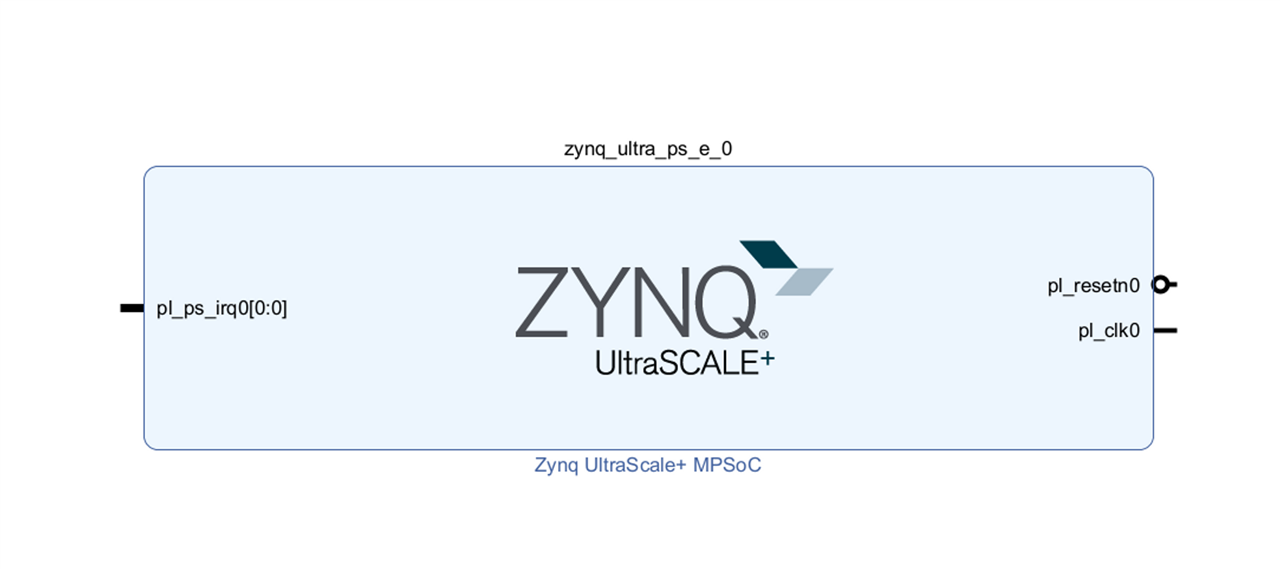
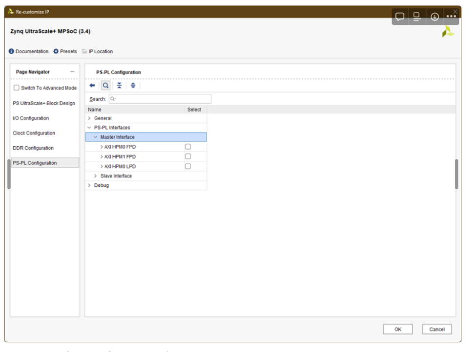
The block design is a very very simple with just a Zynq UltraScale+ block as shown below. We then can double click to customize it and uncheck of the HPM interfaces under PS-PL Interface as we won’t be needing those.
We can then generate the hardware and include bitstream in it as that is all we need from Vivado.
3. Blinking the LEDs using Vitis
Then in Vitis, we can create a hello world project using the hardware platform file that we obtained from Vivado and use the following code to blink the f4 user programmable LEDs as shown in the video below.
#include <stdio.h>
#include "platform.h"
#include "xil_printf.h"
#include "xgpiops.h"
#include "xil_printf.h"
#include "sleep.h"

#define GPIO_DEVICE_ID XPAR_PSU_GPIO_0_DEVICE_ID  // The device ID for the GPIO device

int main() {
	int LED[4] = {17, 18, 19, 20};
	int led_ctr = 0;
    XGpioPs Gpio;
    XGpioPs_Config *ConfigPtr;
    int Status;

    // Initialize the GPIO driver
    ConfigPtr = XGpioPs_LookupConfig(GPIO_DEVICE_ID);
    if (ConfigPtr == NULL) {
        xil_printf("GPIO Lookup failed\n");
        return XST_FAILURE;
    }

    Status = XGpioPs_CfgInitialize(&Gpio, ConfigPtr, ConfigPtr->BaseAddr);
    if (Status != XST_SUCCESS) {
        xil_printf("GPIO Initialization failed\n");
        return XST_FAILURE;
    }

    for (int i = 0; i <= 3; i++) {
    	/* Set the direction and enable output */
    	XGpioPs_SetDirectionPin(&Gpio, LED[i], 0x1);
  	    XGpioPs_SetOutputEnablePin(&Gpio, LED[i], 0x1);
  	    XGpioPs_WritePin(&Gpio, LED[i], 0);
    }


    while(1) {
        XGpioPs_WritePin(&Gpio, LED[led_ctr], 1);
        xil_printf("LED ON!");
        sleep(1);
        XGpioPs_WritePin(&Gpio, LED[led_ctr], 0);
        xil_printf("LED OFF!");
        sleep(1);

        led_ctr++;
        if (led_ctr == 4) { led_ctr = 0;}
    }

    return 0;
}
Result.
The demo of the project can be found here.
5. Conclusion
In the first blog we created a very simple design and blinked the four LEDs connected to the PS side of the Ultra96v2 SBC. In the next one, we will extend this to include the FPGA.