


Welcome to blog 5 for the Ultra96-V2 development board. In this blog, we'll dive into interfacing an LCD Click board with the Ultra96-V2, allowing you to display information, messages, or graphics on an LCD screen. Let's get started!

LCD mini click displays 2x16 monochrome characters on an LMB162XFW LCD display. It features the MCP23S17 port expander and the MCP4161 digital potentiometer, both from Microchip. LCD mini click is designed to communicate with both 3.3V or 5V capable MCUs. The logic voltage level selection is done by the PWR SEL onboard SMD jumper. The 5V rail from the mikroBUS is used directly for powering up the included LCD screen. The click board communicates with the target microcontroller over the SPI interface and the following pins on the mikroBUS line: PWM, INT, RST, AN.
01 void main()
02 {
03     system_init();
04
05     SPI_Lcd_Out(1, 6, "mikroE");
06     SPI_Lcd_Out(2, 2, "LCD mini click");
07
08     set_bcklight(0xFF);
09     set_contrast(0xDF);
10
11     Delay_ms(5000);
12
13     while (1)
14     {
15         set_bcklight(value);
16         set_contrast(value);
17
18         value++;
19         delay_ms(40);
20     }
21 }

Launch Vivado and open your existing project from the previous blogs. In the block diagram, add an AXI GPIO IP block to control the LCD Click board. Connect the AXI GPIO to the appropriate pins on the LCD Click board. Run "Generate Bitstream" and "Export Hardware" in Vivado.

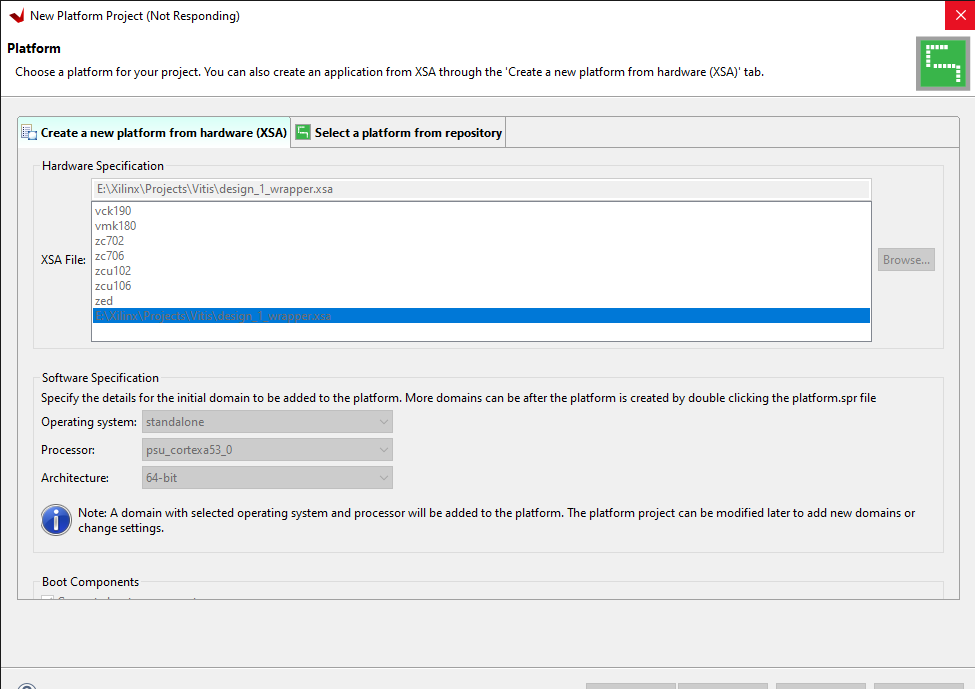
Launch Xilinx Vitis and open your existing FPGA design project for the Ultra96-V2 board. If you haven't created a project yet, complete the necessary steps to create a new project and add your design files.
| {gallery} |
|---|
|
|
 |
//----------------------------------------------------------------------------
//      _____
//     *     *
//    *____   *____
//   * *===*   *==*
//  *___*===*___**  AVNET
//       *======*
//        *====*
//----------------------------------------------------------------------------
//
// This design is the property of Avnet.  Publication of this
// design is not authorized without written consent from Avnet.
//
// Please direct any questions to:  technical.support@avnet.com
//
// Disclaimer:
//    Avnet, Inc. makes no warranty for the use of this code or design.
//    This code is provided  "As Is". Avnet, Inc assumes no responsibility for
//    any errors, which may appear in this code, nor does it make a commitment
//    to update the information contained herein. Avnet, Inc specifically
//    disclaims any implied warranties of fitness for a particular purpose.
//                     Copyright(c) 2013 Avnet, Inc.
//                             All rights reserved.
//
//----------------------------------------------------------------------------
//
// Create Date:         Oct 25, 2013
// Design Name:         LED Dimmer Application
// Module Name:         main.c
// Project Name:        Zynq Software SpeedWay
// Target Devices:      Zynq-7000
// Hardware Boards:     MicroZed/ZedBoard
//
// Tool versions:       Vivado/SDK 2013.3
//
// Description:         Zed LED Dimmer Example
//
// Dependencies:
//
// Revision:            Oct 25, 2013: 1.00 Initial version
//
//----------------------------------------------------------------------------

/***************************** Include Files *********************************/

#include "xparameters.h"
#include "xil_io.h"
#include "xstatus.h"
#include "xscugic.h"
#include "xil_exception.h"

/************************** Constant Definitions *****************************/
/* The following constant maps to the name of the hardware instances that
 * were created in the Vivado system design. */
#define PWM_BASE_ADDRESS               0xA0010000

/* The following definitions are related to handling interrupts from the
 * PWM controller. */

#define INTC_PWM_INTERRUPT_ID	       XPAR_FABRIC_PWM_W_INT_0_INTERRUPT_OUT_INTR
#define INTC		                   XScuGic
#define INTC_HANDLER	               XScuGic_InterruptHandler
#define INTC_DEVICE_ID	               XPAR_SCUGIC_0_DEVICE_ID

/************************** Variable Definitions *****************************/

/*
 * The following are declared globally so they are zeroed and so they are
 * easily accessible from a debugger
 */

/* LED brightness level is now global to make is visble to the ISR. */
volatile u32 brightness;
/* The Instance of the Interrupt Controller Driver */
static INTC Intc;

void PWMIsr(void *InstancePtr)
{
    /* Inform the user that an invalid value was detected by the PWM
     * controller. */
    print("PWM Value exceeded, brightness reset to zero. Please enter new value: \r\n");

    /* Set the brightness value to a safe value and write it to the
     * PWM controller in order to clear the pending interrupt. */
    brightness = 0;
    Xil_Out32(PWM_BASE_ADDRESS, brightness);
}

/****************************************************************************/
/**
* This function sets up the interrupt system for the PWM dimmer controller.
* The processing contained in this function assumes the hardware system was
* built with an interrupt controller.
*
* @param	None.
*
* @return	A status indicating XST_SUCCESS or a value that is contained in
*		xstatus.h.
*
* @note		None.
*
*****************************************************************************/
int SetupInterruptSystem()
{
	int result;
	INTC *IntcInstancePtr = &Intc;

	XScuGic_Config *IntcConfig;

	/* Initialize the interrupt controller driver so that it is ready to
	 * use. */
	IntcConfig = XScuGic_LookupConfig(INTC_DEVICE_ID);
	if (IntcConfig == NULL)
	{
		return XST_FAILURE;
	}

	/* Initialize the SCU and GIC to enable the desired interrupt
	 * configuration. */
	result = XScuGic_CfgInitialize(IntcInstancePtr, IntcConfig,
					IntcConfig->CpuBaseAddress);
	if (result != XST_SUCCESS)
	{
		return XST_FAILURE;
	}

	XScuGic_SetPriorityTriggerType(IntcInstancePtr, INTC_PWM_INTERRUPT_ID,
					0xA0, 0x3);

	/* Connect the interrupt handler that will be called when an
	 * interrupt occurs for the device. */
	result = XScuGic_Connect(IntcInstancePtr, INTC_PWM_INTERRUPT_ID,
				 (Xil_ExceptionHandler) PWMIsr, 0);
	if (result != XST_SUCCESS)
	{
		return result;
	}

	/* Enable the interrupt for the PWM controller device. */
	XScuGic_Enable(IntcInstancePtr, INTC_PWM_INTERRUPT_ID);

	/* Initialize the exception table and register the interrupt controller
	 * handler with the exception table. */
	Xil_ExceptionInit();
	Xil_ExceptionRegisterHandler(XIL_EXCEPTION_ID_INT,
			 (Xil_ExceptionHandler)INTC_HANDLER, IntcInstancePtr);

	/* Enable non-critical exceptions */
	Xil_ExceptionEnable();

	return XST_SUCCESS;
}

/************************** Main Code Entry **********************************/
int main(void)
{
    int status = XST_SUCCESS;
    u32 value = 0;
    u32 period = 0;
    brightness = 0;

    /* Initialize the LED Dimmer controller to a safe PWM value. */
    Xil_Out32(PWM_BASE_ADDRESS, 0);

    /* Setup the interrupts such that interrupt processing can occur.  If an
     * error occurs while setting up interrupts, then exit the application. */
    status = SetupInterruptSystem();
    if (status != XST_SUCCESS)
    {
        return XST_FAILURE;
    }

    /* Now that the hardware has been initialized, continuously loop while
     * prompting the user for updates to the brightness level. */
    while (1)
    {
        /* Prompt the user to select a brightness value ranging from
         * 0 to 9. */
        print("Select a Brightness between 0 and 9\n\r");

        /* Read an input value from the console. */
        value = inbyte();

        /* Convert the input ASCII character to an integer value. */
        period = value - 0x30;

        /* Print the input value back to the console to provide some
         * feedback to the user. */
        xil_printf("Brightness Level %d selected\n\r", period);

        /* Since the LED width is 1e6 clk cycles, we need to normalize
         * the period to that clk.  Since we accept values 0-9, that will
         * scale period from 0-999,000.  0 turns off LEDs, 999,000 is full
         * brightness. */
        brightness = period * 110000;

        /* Write the duty_cycle width (Period) out to the PL PWM
         * peripheral. */
        Xil_Out32(PWM_BASE_ADDRESS, brightness);
    }

    return status;
}
Ensure your Ultra96-V2 board is powered off. Connect the LCD Click board to the Click Mezzanine connector on the Ultra96-V2. Power on your Ultra96-V2 board.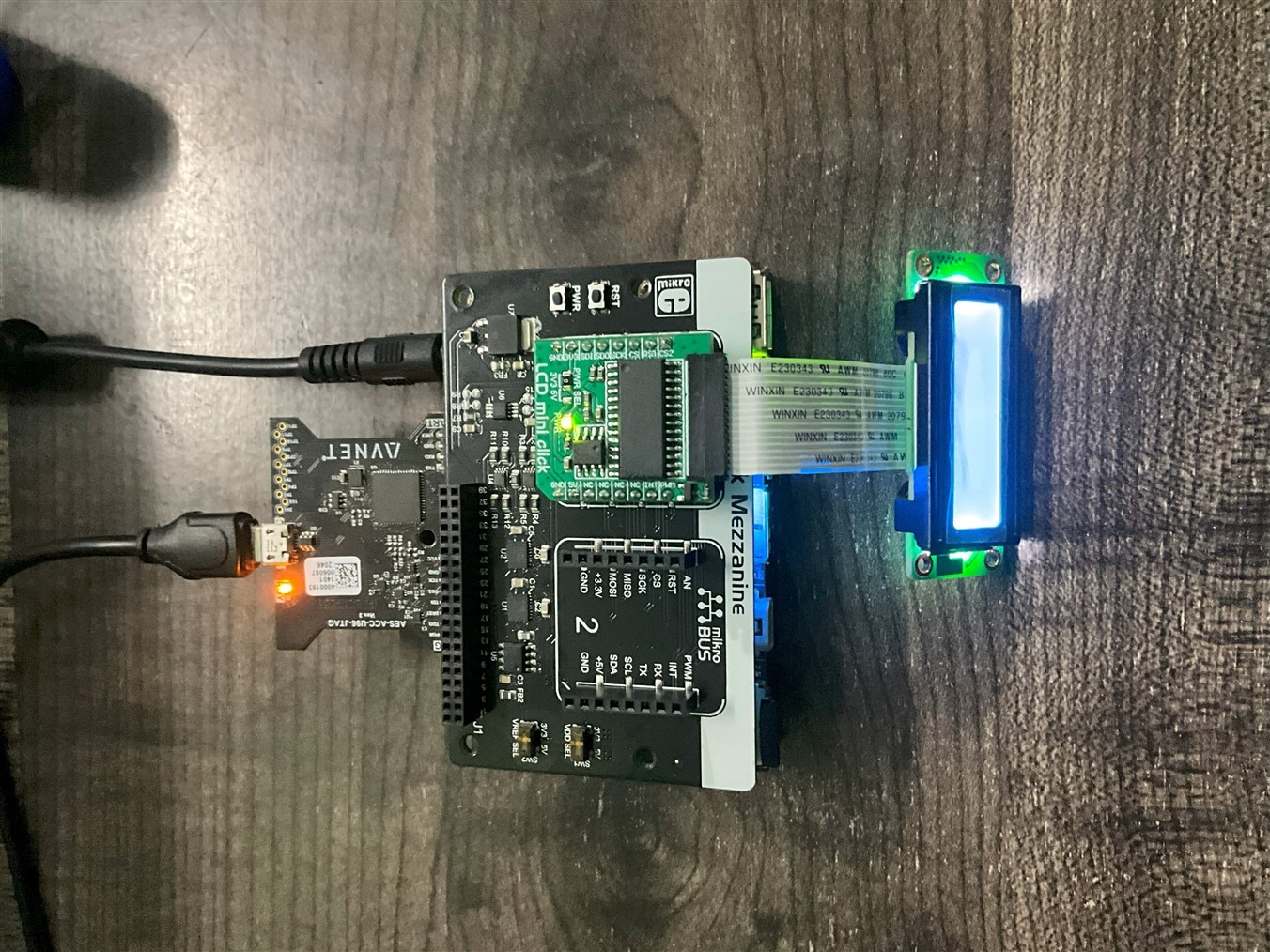

We've successfully interfaced the LCD Click board with the Ultra96-V2 development board. Stay tuned for our final blog in this series, where we'll continue to explore exciting features and interfaces for the Ultra96-V2 board. Happy experimenting!