element14 Community
element14 Community
    Register Log In
  • Site
  • Search
  • Log In Register
  • About Us
  • Community Hub
    Community Hub
    • What's New on element14
    • Feedback and Support
    • Benefits of Membership
    • Personal Blogs
    • Members Area
    • Achievement Levels
  • Learn
    Learn
    • Ask an Expert
    • eBooks
    • element14 presents
    • Learning Center
    • Tech Spotlight
    • STEM Academy
    • Webinars, Training and Events
    • Learning Groups
  • Technologies
    Technologies
    • 3D Printing
    • FPGA
    • Industrial Automation
    • Internet of Things
    • Power & Energy
    • Sensors
    • Technology Groups
  • Challenges & Projects
    Challenges & Projects
    • Design Challenges
    • element14 presents Projects
    • Project14
    • Arduino Projects
    • Raspberry Pi Projects
    • Project Groups
  • Products
    Products
    • Arduino
    • Avnet Boards Community
    • Dev Tools
    • Manufacturers
    • Multicomp Pro
    • Product Groups
    • Raspberry Pi
    • RoadTests & Reviews
  • Store
    Store
    • Visit Your Store
    • Choose another store...
      • Europe
      •  Austria (German)
      •  Belgium (Dutch, French)
      •  Bulgaria (Bulgarian)
      •  Czech Republic (Czech)
      •  Denmark (Danish)
      •  Estonia (Estonian)
      •  Finland (Finnish)
      •  France (French)
      •  Germany (German)
      •  Hungary (Hungarian)
      •  Ireland
      •  Israel
      •  Italy (Italian)
      •  Latvia (Latvian)
      •  
      •  Lithuania (Lithuanian)
      •  Netherlands (Dutch)
      •  Norway (Norwegian)
      •  Poland (Polish)
      •  Portugal (Portuguese)
      •  Romania (Romanian)
      •  Russia (Russian)
      •  Slovakia (Slovak)
      •  Slovenia (Slovenian)
      •  Spain (Spanish)
      •  Sweden (Swedish)
      •  Switzerland(German, French)
      •  Turkey (Turkish)
      •  United Kingdom
      • Asia Pacific
      •  Australia
      •  China
      •  Hong Kong
      •  India
      •  Korea (Korean)
      •  Malaysia
      •  New Zealand
      •  Philippines
      •  Singapore
      •  Taiwan
      •  Thailand (Thai)
      • Americas
      •  Brazil (Portuguese)
      •  Canada
      •  Mexico (Spanish)
      •  United States
      Can't find the country/region you're looking for? Visit our export site or find a local distributor.
  • Translate
  • Profile
  • Settings
Path to Programmable 3
  • Challenges & Projects
  • Design Challenges
  • Path to Programmable 3
  • More
  • Cancel
Path to Programmable 3
Blog UART Test - Serial Message on Ultra96-V2 - Blog 2
  • Blog
  • Forum
  • Documents
  • Leaderboard
  • Files
  • Members
  • Mentions
  • Sub-Groups
  • Tags
  • More
  • Cancel
  • New
Join Path to Programmable 3 to participate - click to join for free!
  • Share
  • More
  • Cancel
Group Actions
  • Group RSS
  • More
  • Cancel
Engagement
  • Author Author: rahulkhanna
  • Date Created: 4 Sep 2023 1:53 PM Date Created
  • Views 1151 views
  • Likes 5 likes
  • Comments 0 comments
  • ultra96v2
  • design challenge
  • vivado
  • Ultra96-V2 Board
  • design competition
  • Path to Programmable III
  • Path to Programmable 3
  • Training blog
Related
Recommended

UART Test - Serial Message on Ultra96-V2 - Blog 2

rahulkhanna
rahulkhanna
4 Sep 2023
UART Test - Serial Message on Ultra96-V2 - Blog 2

In this blog, we will be working on the process of printing messages to the serial port on the Ultra96-V2 development board. Serial communication is a fundamental method for interacting with embedded systems, allowing you to monitor and debug your FPGA designs. We'll be able to send messages from your FPGA design to a terminal or serial monitor connected to the Ultra96-V2 board.

Launch Xilinx Vivado and open your existing FPGA design project for the Ultra96-V2 board. If you haven't created a project yet, complete the necessary steps to create a new project and add your design files.

{gallery}Creating Vivado Project

image

image

image

image

image

Open the ZynqDesign project and open the Block design, design_1.bd.

Double click on the Zynq ultrascale+ MPSoC to customize IP. We will be configure the Zynq MpSoC step by step as shown below.

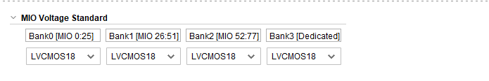
{gallery}Configuring Zynq MpSoC

image

Set the all bank voltages to LVCMOS 1.8V 

image

Enable UART 1 and set the I/O to MIO0 .. 1

image

Check the "Switch to Advanced Mode" and set UART1 baud rate to 115200. 

To configure the memory and clocks for Zynq MPSoC, Click on the Clock Configuration. 

{gallery}Configuring Memory & Clocks

image

Verify the input clock frequency - 33.333 MHz 

image

Verify the following in the output clocks.

ACPU frequency - 1200 MHz

CPU R5 frequency - 500 MHz

GPU frequency - 600 MHz

image

Disable the PS-PL reset by unchecking the Fabric Reset Enable. 

image

Enable the DDR Controller and switch the memory type to LPDDR4. 

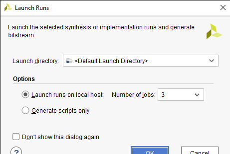
Proceed to implement the design by clicking on "Run Implementation" in Vivado. Once implementation is successful, generate the bitstream by clicking on "Generate Bitstream. Click Next in the Export Hardware Platform, on the next page check the Include bitstream box and click OK.

{gallery}Exporting Hardware

image

image

Creating Vitis Project 

Create Platform Project by selecting File → New → Platform Project. Name the platform project as “Ultra96_Platform”. 

Select the .xsa file generated in the previous step. This will create a new platform from hardware using the design_1_wrapper.xsa file.  

{gallery}My Gallery Title

image

image

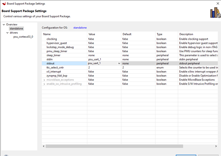
Click Modify BSP Settings on the standalone on psu_cortexa53_0. Click standalone in the Board Support Package window. Make sure that stdin and stdout are set to the psu_uart_1 peripheral. 

image   image

Right Click on the Ultra_96_Platform and select build the platform. 

image

How let's create a new application project by selecting File → New → Application Project. Make sure that the ultra96_platform is selected. I've named the Application Project as “HelloWorld". Select Hello World from the Available Templates field. Click Finish.

{gallery}Creating Application Project on Vitis
image
image

Right-click on the HelloWorld Application and select Build. Right-click on the application and select Run As → Launch Hardware to program the FPGA.  

{gallery}Programming FPGA

image

image

Connect the USB-to-UART cable to the JTAG UART connector on the Ultra96-V2 board. The other end of the cable should be connected to your computer.

image

Open a terminal or serial monitor program on your computer. Configure the settings to match the UART communication parameters set in your FPGA design. Once the FPGA design is running on the Ultra96-V2 board, your messages will be sent to the serial monitor. You should see the messages displayed on the terminal or serial monitor.

image

We have successfully implemented serial communication and printed messages from your FPGA design on the Ultra96-V2 board to a terminal or serial monitor. Feel free to experiment further by sending different messages and expanding the functionality of your FPGA design using the UART module.

.

  • Sign in to reply
element14 Community

element14 is the first online community specifically for engineers. Connect with your peers and get expert answers to your questions.

  • Members
  • Learn
  • Technologies
  • Challenges & Projects
  • Products
  • Store
  • About Us
  • Feedback & Support
  • FAQs
  • Terms of Use
  • Privacy Policy
  • Legal and Copyright Notices
  • Sitemap
  • Cookies

An Avnet Company © 2025 Premier Farnell Limited. All Rights Reserved.

Premier Farnell Ltd, registered in England and Wales (no 00876412), registered office: Farnell House, Forge Lane, Leeds LS12 2NE.

ICP 备案号 10220084.

Follow element14

  • X
  • Facebook
  • linkedin
  • YouTube