


Hello again,
In lab 5 we finally connect the MiniZed and flash it with a program! Closely followed by lab 6 in which we set up the first stage bootloader - FSBL. This will allow the MiniZed to run "untethered" and not plugged in with the JTAG connector to the computer run our program.
About:
Through Avnet, Xilinx and Element14, a training program to learn about the Zynq 7000 platform which is System On Chip combining an FPGA with an ARM processor. This comes to the students as complete development board packed with goodies like a wireless chip from MuRata (BT/BTLE/WIFI), 8GB Flash memory, onboard RAM, USB to JTAG (JTAG programmable over USB), Arduino-style headers (3.3V compatible only), Microphone, Bi-Color LED, and two additional expansion ports.
See all blog posts for this training here.
Lab 5- Connecting!
In this section, we connect and download our application over JTAG; then run it. We will also learn the debug utilities of the SDK - setting breakpoints and stepping through code; viewing the call stack, and other useful features. Being that our FPGA uses volatile memory, we would normally be storing the program into flash memory or on an SD card. For initial test and debug, we will be using the SDK to function like that via the JTAG interface and we can run initial code without having to program it into flash. In the following lab, we'll download to flash to run 'untethered'.
Therefore; one of our initial steps is setting the DIP switch on the board to "J"; telling it to boot from JTAG instead of from Flash. I noticed that even at this stage in the training, my MiniZed still has its 'Hello World' programmed into the flash. This is a simple program that reads the on-board microphone and changes an LED brightness based on the sound level.
We open the SDK after having our board plugged in and press "Program FPGA" (the button highlighted below).
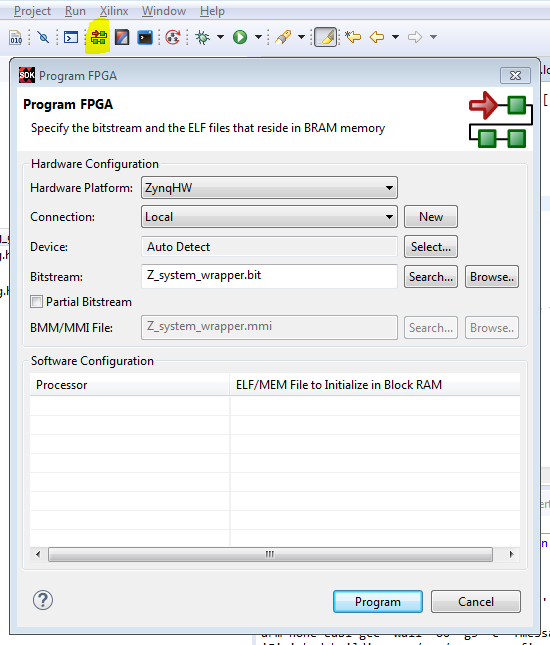
This sends the current loaded application in the SDK down to the board. Again - this is just held in volatile memory and NOT saved to the board itself. The bitstream is written when the "Program" button is pressed.
The Hello Zynq program is run (right click on top level folder in Project Explorer --> Run As --> Run Configuration --> New --> Run) and we get our output shown in the serial console. (I'm running PuTTY as my console application).
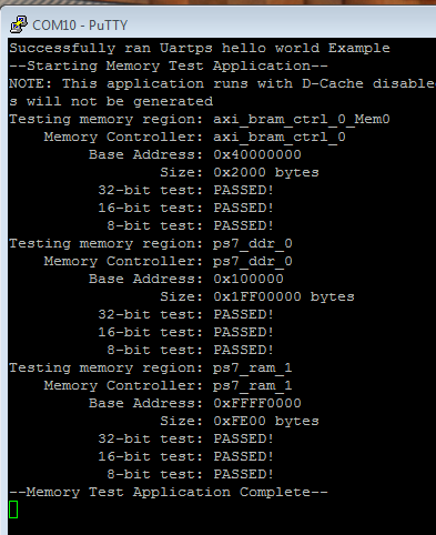
I also then ran the quick memory tester application which tests the first 4K in BRAM, DDR, and regular RAM. The Test_Memory_FullDDR also also run and it validates a full 1mb of DDR memory.
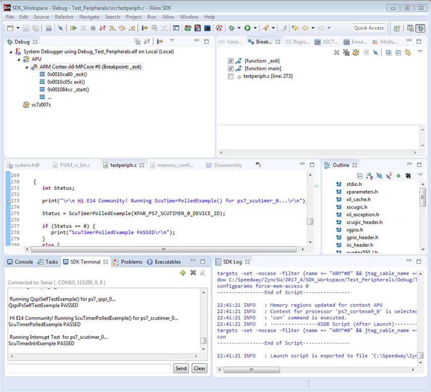
The last portion of this is running the debugger. Using similar methods to the "run as", we right click our program in the explorer and hit "Debug as" and then "New"; "Debug". The difference here is that the SDK "perspective" changes to the "debug" perspective. This feels a lot like Visual Studio when you "F5" to debug a program. The bitstream is written to the MiniZed and we have a new view of the SDK. We can set breakpoints, step through code, pause execution, check variable status/values, and manually check all sorts of other things if we chose. Another difference is that I am able to close PuTTY and use a terminal directly within the SDK's Debug perspective as a tab. This felt much more useful and more complete for this type of debugging.
We are also presented with our source code, the C file, and I was able to edit directly in the debug window then "relaunch" the debugger and try out the changes. This was very powerful as it would allow a fast way to work through code changes and test things.
That was it for Lab 5 - On to the next one!
Lab 6 - First Stage Bootloader (FSBL)
This lab focuses on loading our application to the Flash (non-volatile) memory so that we can unplug from our computer and run the board by itself. One thing I learned in this lesson was that the Zynq7000 series; although it is both an ARM processor AND an FPGA; it is a "processor first" chip. This means that the CPU must boot in order for the PFGA to read in its program. As opposed to traditional FPGAs which had an ability to 'on their own' connect to external flash to download the program without the need for a traditional microprocessor. So even a most basic program must be on the CPU for the FPGA to run. A fully stand-alone FPGA is not supported.
The FSBL first can initialize the PLL, External memory, and MIO. It also can configure the PL with our bitstream; then finally runs our application. So this file is really just a very basic set of instructions used to get things ready for the actual code to be able to run.
The SDK can generate the FSBL automatically based on our hardware package and our program.
After the FSBL runs, a Second Stage Boot Loader runs; which can launch the OS such as PetaLinux on the Zynq. It is important to note also that the options for the SSBL include USB, GigE which aren't options for the FSBL (and even more limited options on the MiniZed. So we can almost "PXE Boot" the device - FSBL could provide some basic computer networking information, then we could launch a program which was based on a network server (if I'm understanding this correctly). Very cool!
The FSBL can be created by the SDK, and/or manually; however it is effectively limited to 192k in size for basic implementations. There are some ways around it (running directly from memory) but embedded programmers should pay attention to this.
So in summary, the FSBL needs to be created then loaded into QSPI Flash memory; which will allow the chip to boot properly and run our program.
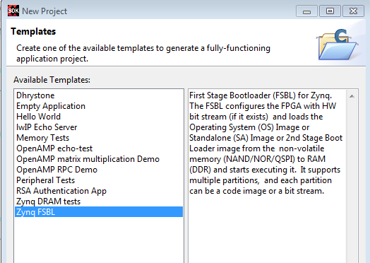
Creating the FSBL from template
This is pretty straight-forward. From within SDK, we click "File--> New Application Project --> then chose FSBL from the list of available templates. One change is that we tell SDK to create a new BSP (Board Support Package) instead of using the existing one. This is because the requirements of the FSBL are different from the regular BSP as it includes a file system library (xilffs).
These libraries weren't present in the regular BSP:
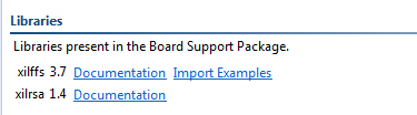
My FSBL came out at 164,480 bytes (~160k). That is within the limit of 192k of the FSBL memory.
We then check the Properties for the build. There are numerous options for compressing down the build size and for setting the debug level. The default is No Optimization, and Debug level to Maximum. For a final deliverable, then these should certainly change to be more... embedded 
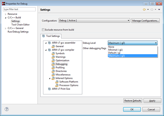
My release file came out at 157,500 bytes (153k); so about 5% smaller.
That was about it for this lesson. We examined some of the generated files, but won't be uploading to the board until the next lab - Lab 7.
We did find the location where the FSBL hands off to the SSBL in a file called main.c:
/*
* FSBL handoff to valid handoff address or
* exit in JTAG
*/
FsblHandoff(HandoffAddress);
Until next time!
- James
Top Comments