


In Path to Programmable Blog 4 - Adding a PL Peripheral & using PS DMA, we added Block RAM to the PL and connected it to the PS using the AXI interface. We also looked at how we can use DMA to speed up transfers.
The Block RAM was added to the PL using Xilinx's IP that is bundled with Vivado - which was automatically configured and connected.
When working on custom designs, we need to generate 'IP' of our own i.e. somehow link registers/datapaths in our HDL to the AXI interface so that they can be accessed by the PS on the Zynq-7000, or any other IP for that matter. This also applies to the standard FPGA families like the Spartan, Artix, Kintex & Virtex since the Microblaze softcore also uses AXI.
HW Chapter 8 video: Creating Custom IP
The video went over how Vivado lets you generate your own IP that can be added to the catalog, and even shared with others. It bundles the source code, simulation models, documentation etc. and Vivado has a wizard that lets you easily create all of this.


Vivado automatically generates 2 files:
- the 'top' level source which encapsulates the entire 'IP' project containing HDL.
- the slave AXI-4 Lite Interface, which in instantiated in the top level file, and handles the AXI side of things.


The code generated is similar to something that ST's CubeMX tool generates and contains code combined with commented regions where users are supposed to add their own.
All of this will make a lot more sense after Lab 7!
Lab 7 - Adding Custom IP to Vivado IP Catalog
To create new IP, open the wizard: Tools > Create and Package New IP. Vivado gives you options to package your current project, or a certain block design as IP, but opt to 'Create a AXI4 Peripheral'


The next options are name of the IP, location etc.
After this is configuration where number of 16 AXI interfaces, select different modes, data widths, number of registers etc. can be set.
Once the IP has been created, search for it in the IP Catalog & edit it. This opens up a new Vivado project


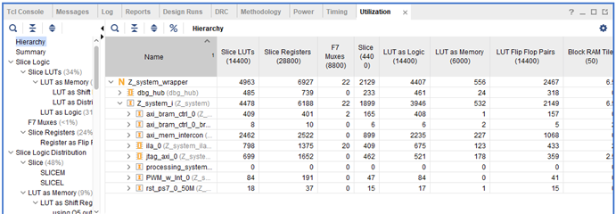
The hierarchy of the two automatically generated files is as shown. The x_AXI file contains the logic needed to talk to the AXI interface (addressing/read/write), and the top level file (PWM_w_Int_v1_0.vhd) simply instantiates the file that handles AXI as a component (in VHDL). The top level file transparently passes all the AXI interfaces through to the _AXI file, so although all the AXI ports appear in the entity (I/O) of the top level (wrapper) file, the top level file doesn't do anything as far as AXI is concerned.
This encapsulates all the AXI related logic in the _AXI file, and the wrapper simply 'imports' it and uses it (we'll come to how it's used soon) - just like you 'import' drivers/libraries to use parts/interfaces in embedded development in C (or Python for the RPi).

Next, we imported a file containing the user logic i.e. the HDL design. This was included with the training material - "PWM_Controller_Int.v" (Verilog code).
To import any VHDL/Verilog code into the top level wrapper (PWM_w_Int_v1_0.vhd), we first instantiate it (which defines what are the I/O connections), and then add a component (which is an instance of the imported 'structure', and determines how the I/O of that structure are connected to the top level wrapper to which it is being imported).
After adding lines of code to wire up the logic & adding a couple of ports, we end up with this:
- The AXI signals which are exposed by the top level wrapper get connected by the block automation assistant.
- We used the AXI clk & reset signals for the custom HDL.
- We modified the AXI wrapper to bring out 'slave_reg0', which is then connected to the DutyCycle input of the PWMController HDL. It is memory mapped, so any program running on the PS can write a value to this address, and it will get passed to register/input of our custom HDL, which in turn will set a value in hardware.


We then move on to packaging the IP, which opens up a wizard for defining file groups for synthesis, simulation and setting customization parameters - which will allow the user to customize the design when he/she is using the wizard to import the IP. We also modified the IP so that certain signals are recognized as clocks, interrupts etc so that Block Automation works better. After this, review and package the IP.
Now that the IP is packaged, we can import it (like with did with Zynq7PS, BRAM Controller, AXI) and use it in our Block Design. Running Block Automation adds another AXI Master to the AXI Interconnect, and the AXI ports in our IP are automatically connected to it. The clock & reset signals also get connected. We then customize the Zynq7PS Block to enable a Interrupt line, and then manually connect it.
The instructions ask for an ILA (Integrated Logic Analyzer) to be connected - first search for the IP, add it, select the number of probes we need, the width of each one and then manually connect the probe to the signals.
We were then asked to add a JTAG-AXI core which we will be using a little later.
The final task left to do is connect the LED output of the PWM Generator. Since we need to 'expose' this externally, we right click on it and make a 'port' which creates the external port as shown. We then import the constraints file which has definitions that link HDL/Port names to the actual I/O pins on the physical package.

The design is larger than the previous ones, so it took around 10-15 minutes to synthesize & implement.

Progress:

