


I tried out a couple of things that weren't a part of the Path to Programmable Course Syllabus, but I thought I'd share them:
- How to setup the clocks for PL-only designs with the MiniZed
- 3-bit VGA output from the MiniZed without a PMOD.
MiniZed Clocking
As far as trial runs are concerned, running a PL-only design follows the same process as Xilinx's non-SoC parts like the Spartan & Artix: instantiate all HDL source code in a top level wrapper, assign the I/O pins (constraints make this easy), and generate a bit-stream. Flash the bit-stream to the board using the Vivado hardware manager, and you're good to go: the design starts executing as soon as it's uploaded to the board.
Combinational logic circuits will work right away, and while sequential/clocked designs will also work, you need to feed in a clock signal as an input.
Most FPGA boards have an oscillator connected to one of the clock capable pins, which then feeds the clock buffers and clocking hardware within the FPGA: MMCMs, PLLs, clock routing channels and so on.
Zynq-7000 parts also work similarly, except in most cases there are 2 clocks fed to the package: one for the PS, and one for the PL as documented over here.
The PL clock source will work immediately since it's always on, but while the PS clock might be active, the PS needs to boot so that the PS_CLK can be configured and routed to the PL via PL_FCLKx.


The MiniZed doesn't have an CLK source connected to the PL side, so it must be obtained from the PS, which means the PS must run for the PL side to receive a clock, whether or not the PS executes any code.
Create a new project, a new block design & add the Zynq7 Processing System. If the board definition files for the MiniZed were imported correctly, and if the MiniZed was selected as the 'Board' while creating the project, the PS7 configuration wizard will have most of it's values pre-configured correctly (DRAM type, DRAM trace lengths, MIO pins etc.) which makes things easy.
The only changes I made were to enable the 4 PL Fabric Clocks (though I need only one).
After adding the clocks, the FCLK_CLK0 pins will get added to the Zynq7 PS block diagram, except they won't be connected to anything at first (all will look like FCLK_CLK0).


The clocks will work, and can be connected to any other blocks that are added to the Block Design, but if we're going to be managing the project using HDL code instead of a block design, the clocks need to be brought out.
The other method would be to import the RTL code and manage everything using a block design, and later generate a wrapper of the whole design, but let's go with the first method.
To make a port external, right click on it click on 'create port', which gives you a couple of more options than 'make external'.
Since the entire project is managed using HDL at a high level, block designs need to be wrapped i.e. represented by HDL, which is automatically generated by Vivado when 'Generate HDL Wrapper' is clicked.
Here's what the design looks like now:

As you can see, all the ports of the block design (in this case, it's only the Zynq7 PS) which were external have brought out of the encapsulating block. Normally, this would only consist of the DDR & Fixed IO (by default), but since we make the FCLK_CLKx ports external, they're also exposed. The VHDL wrapper is automatically generated, and all the ports are added to the entity as shown (the entity contains all the ports that go into or come out of a block, and defines their names, widths & directions).
To use this, I created a new VHDL file which I made my 'top' module i.e. the highest file that wraps everything else. I then instantiated the automatically generated Zynq_wrapper.vhd file in it, and copied over the entity of the automatically generated wrapper to my top file to 'expose' the DDR & FIXED I/O connections at the highest level, since Vivado will map these to package pins.
Here, top.vhd has the DDR & FIXED I/O pins that come out of the Zynq wrapper in its entity, and it makes them external. However, since 'top.vhd' wraps the entire design, it also contains other blocks of logic in addition to the Zynq wrapper, which in this case are the 'VGADemo' & 'PL_Heartbeat' blocks.
FCLK3 which is brought out from the Zynq wrapper doesn't need to go to a pin, which is why it is not included in the entity of the 'top.vhd' file and because of this it doesn't go to a port in the diagram. It is used internally (w.r.t. to the top file), and is routed to the 'PL_HeartBeat' & 'VGADemo' blocks.
Along similar lines, the switch, LED & VGA outputs are connected to actual pins, so they get added to the entity.


Moving on, the first bit of code I tested was 'PL_Heartbeat' which has two outputs:
- PL_LED_R simply copies the value of PL_SW. This can tell me whether the PL part is programmed (toggling the switch should toggle the LED).
- PL_LED_G is a blinky that uses the 25 Mhz clock from the PS. If The LED blinks, it means that the PL has been programmed, and that the PS was correctly configured and that the PL clock sourced from the PS is up and running since it's the only clock source for the blinky.
After implementing this, I programmed it to the board using the Vivado Hardware Manager. The 'Done' LED on the MiniZed lit up, which meant that the PL was programmed. The PL_LED_R toggled when the switch was toggled, which confirmed this.
However PL_LED_G remained off, which was expected because programming the PL over JTAG does not boot up the PS. To boot up the PS, export the project to Xilinx SDK and create any application - I used an empty one without any source code. As soon as the application is run, PL_LED_G starts blinking, signifying that the PS clock has been routed to the PL as expected.
You can make changes to the HDL code, but you don't need to keep exporting it in order to run the code since any logic implemented in the FPGA fabric is part of the bitstream, which can be programmed from Vivado itself. Since we don't have a PS side design, the Xilinx SDK side of things remains the same, unless the PS7 settings are changed i.e. new FCLK frequencies.
To make a design like this one work on it's own (run automatically when the FPGA boots up), the FSBL & bitstream will need to be programmed to the non-volatile memory on the MiniZed, and I think we'll be learning how to do this in Module II: Designing Zynq Software
VGA Controller
I won't go into the details of how VGA works nor how a VGA controller needs to be designed, because there are tons of resources.
I used the code from Gianluca Pacchiella's 'Implementing VGA in Verilog' and referred to these as well:
Ken Shirriff: Implementing FizzBuzz on an FPGA
Ken Shirriff: Using an FPGA to generate raw VGA video: FizzBuzz with animation
Embedded Thoughts: Driving a VGA Monitor Using an FPGA
Digilent Inc: VGA Display Controller
In brief, the pixels are scanned pixel by pixel, with the H_SYNC signal being asserted at the end of every row, and V_SYNC being asserted after all the rows have been scanned. The CLK signal is not transmitted, but is used for timing how long each pixel takes. The R, G & B values are transmitted using a dedicated analog channel. Each channel is terminated on the receiver side (monitor/TV) by a 75 ohm resistor and a 0.7V signal represents the peak 'completely on' value. Since we're using 3.3V logic, the 3.3V 'ON' needs to be scaled down to 0.7V, which can be done by inserted a 270 ohm series resistor so that the voltage the receiver sees is ~0.7 [(75*3.3)/(75+270) = 0.71V]
Since VGA is an analog signal, different voltages will represent different colors. To keep things simple, we only use 1-bit per channel, so we can generate 2^(1+1+1) = 8 colors. To improve this, simply add another data output pin per channel, and use a R-2R or binary weighted resistor DAC.
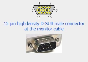
I refered to the VGA pinout diagram @ pinouts.ru.


I didn't have a female D-SUB connector, so I improvised by sliding off the plastic around the female side of standard DuPont 'jumper' cables, wrapping a little tape over the exposed metal side, and sliding it onto the pins of the male VGA cable. They inner diameter of the DuPont female connector matches the outer diameter of the pins on the male side of the VGA cable, so they fit pretty nicely (this also works for the RS-232RS-232 connector as well).
The crocodile clip is use to ground the shield, and all the wires were connected to a breadboard.


The 2 sync signals (HSYNC & VSYNC) from the FPGA go directly to the VGA cable, and the R, G & B signals go through a 270 ohm resistor. The rest of the cables from the connector are the grounds, which are connected together.
PS: It seems like I forgot to connect the grounds to the ground on the MiniZed, but it still worked.

The output was a static image, though I plan on trying out some animations: Ken Shirriff: Using an FPGA to generate raw VGA video: FizzBuzz with animation.
Top Comments
-

Fred27
-
Cancel
-
Vote Up
+2
Vote Down
-
-
Sign in to reply
-
More
-
Cancel
-

avnrdf
in reply to Fred27
-
Cancel
-
Vote Up
+2
Vote Down
-
-
Sign in to reply
-
More
-
Cancel
Comment-

avnrdf
in reply to Fred27
-
Cancel
-
Vote Up
+2
Vote Down
-
-
Sign in to reply
-
More
-
Cancel
Children