


February 2023: Note: This blog post series was originally written in 2018, however, it is still usable as of February 2023 and hopefully onwards. The screenshots are from an older release of Xilinx Vivado software tools, however, the difference is very slight with the more recent tools from Xilinx. Where there is a significant difference, there is a note explaining it, or there are new screenshots.
Introduction
The Path to Programmable training course is intended to help users get up-to-speed using Xilinx parts containing programmable logic and an ARM application processor core inside. These parts are known as Xilinx Programmable System-on-Chip or SoCs. The Xilinx ZYNQ-7000 series is their cost-optimized range.
Using a programmable SoC in theory can make a lot of sense for certain embedded use-cases, because it can act a lot like a custom processor chip. The programmable logic can be used to enhance the capabilities of the processor core, adding features that don’t exist with off-the-shelf processors. As an example, if the product contains a camera module, then it is possible for the programmable logic to handle the camera interfacing and dump into memory the image frames, with no CPU overhead from the processor core.
Often a team is responsible for a product; the programmable logic could be created by a different engineer to the one writing the drivers for the processor, and yet another group of engineers may work on the application code. In the case of this training, it will be just me doing everything. The same goes for my virtual colleagues who are also doing the course at the same time.
I’m _almost_ a newcomer to programmable logic, and certainly a newcomer to using SoCs. I have used some programmable logic before, but not much. The programmable logic is usually created using a hardware description language (HDL). I’ve used a popular HDL called VHDL, with Xilinx programmable logic parts, very briefly for personal projects, with no formal training beyond what a university undergraduate learns. I have extremely basic knowledge of software device drivers too. I think this squarely puts me in the position of many electronics engineers, so I hope my experiences over the next ten weeks are relevant and can help others, or at least not make the same mistakes I do.
This first blog post explores the hardware component of the course!

MiniZed Board
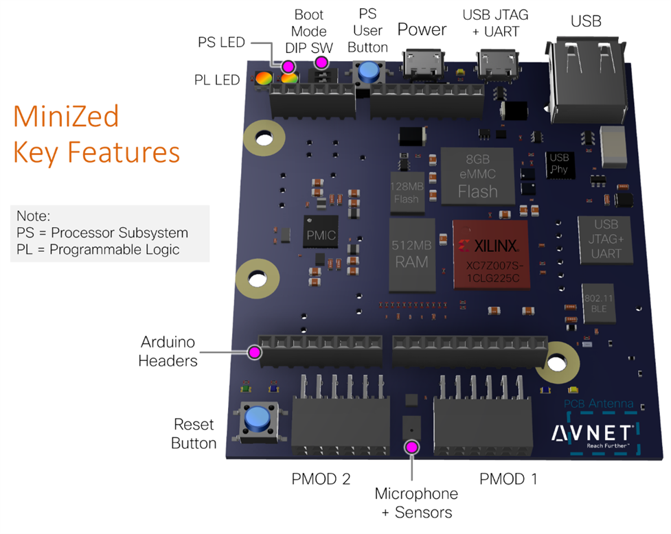
The course consists of one hardware MiniZed boardMiniZed board, and a bundle of files. The board is almost square (77x71x12mm), slightly wider than a Raspberry Pi but a bit shorter. It is a development board and has several handy interfaces for attaching additional circuits. It also has on-board 2.4GHz WiFi and Bluetooth Low Energy (BLE) wireless, USB 2.0 and a few on-board sensors.
There are other boards in the series too - here are some of them.

ZedBoard appears to be an Avnet initiative, along with manufacturers, to develop interest in Xilinx SoCs and associated components. Sometimes distributors need to do such things I feel - another example is Avnet's lighting division, which was initially formed when they noticed that there was a disconnect between traditional light-bulb fixture manufacturers, and LED component manufacturers, during a key phase when the lighting transition was occurring worldwide, and it was (still is) a really successful initiative as I understand.
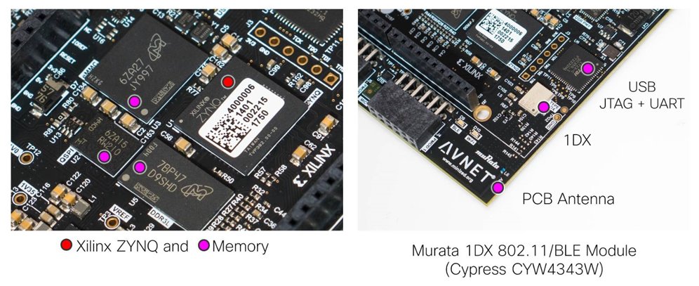
Since the Xilinx ZYNQ chip (XC7Z007S-1CLG225CXC7Z007S-1CLG225C) contains both programmable logic and the ARM applications processor core, the board documentation refers to some peripherals as PS connected, meaning connected to the Processor Subsystem, and some peripherals as PL connected which means they are available to the Programmable Logic to interface with.
As you can see from the diagram above, the processor subsystem (PS) inside the Xilinx chip requires the usual external RAM and Flash memory that any applications processor would need, and so DDR3 RAM and Flash memory chips surround the Xilinx chip. The printed circuit board (PCB) has six layers, which would perhaps be the minimum to be able to make all the interconnections for such a design.
The underside of the board doesn't have much - mainly just supply decoupling capacitors.

There is a heap of files available on the MiniZed website to document the board. Full schematics are available, along with a PDF copy of the PCB layers.
Working with the Board
I’m a newcomer to the development environment which is used to implement the programmable logic and processor subsystem configuration. It is called Xilinx Vivado, available for Linux and Windows. I have used the earlier Xilinx ISE development environment briefly in the past.
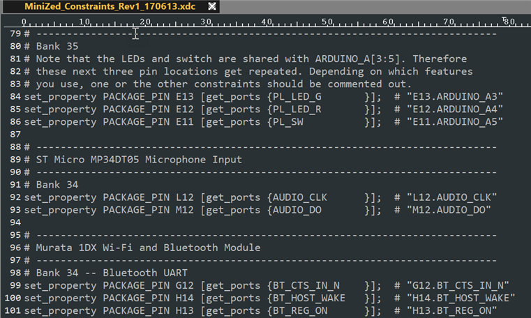
Looking at the files available on the MiniZed website, I could see a Constraints file as expected. In the programmable logic world, this file is responsible for bridging the chip connections to the circuit board design. The PCB designer will lay out the tracks in a certain way, and the development environment will want to know which pins map to which tracks. That is done by the user creating a constraints file (either typing it manually, or using a tool to do the mapping). For instance, if the PCB designer connects pins 1-16 (as an example) as an address bus to external chips, then the constraints file will contain the text that indicate that pins 1-16 are to be referred to as a bus called (say) address_bus in the HDL that will be written by the engineer. In real life, there could be an iterative process where the HDL engineer will tell the schematic and layout designers which pins are preferred, and they will make suggestions back to the HDL engineer about what is feasible electrically.
Another interesting set of files to download were the Board Definition files. These are especially for the MiniZed board, and they tell the Vivado development environment that certain connections are made to the LEDs and buttons, the speed settings for clocks to access memory, and so on. It makes for more friendly development when using a particular board.

For those who wish to make custom enclosures, a 3D CAD ‘STEP’ file is also available to download. It will allow software such as Autodesk Fusion 360 to import in all physical dimensions, so that you can precisely design a case around it.
What’s inside the Xilinx Chip?
As mentioned the Xilinx System-on-Chip contains a processor and programmable logic. I found a diagram which shows the key modules. The top three-quarters of the diagram is the processor subsystem. The lower part is the programmable logic portion.
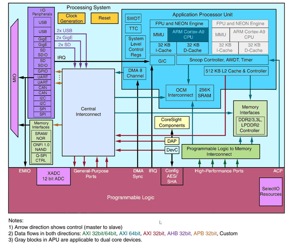
The processor (shown in blue at the top-right) is an ARM Cortex-A9, which has approximately similar capabilities to a BeagleBone Black. But whereas the BBB uses separate processors (called programmable real-time units) for some custom offload capabilities, the Xilinx SoC has the programmable logic to achieve that. It is a crude comparison, but hopefully the Xilinx SoC areas will be zoomed-into in later blog posts too.
The particular SoC on the MiniZed board has a single core Cortex-A9, but other parts in the series have dual cores. The light-yellow area in the center of the diagram is a standard ARM interface for debugging processors, and is accessible via the USB JTAG interface. The SelectIO area at the lower-right refers to input/output pads on the chip, that are configurable to meet many different logic standards. It allows for the Xilinx parts to be compatible with many third party devices, through configuration in the HDL that is written.
The lower-left area shows that there is also a 12-bit ADC on the chip, which was nice to see.
The left purple area contains many in-built peripherals that are directly controlled by the ARM processor. They can be brought out of the chip onto pins, through the Multiplexed Input/Output (MIO) interface.
Summary and Next Steps
The board is very low-cost (approximately $100 or £70GBP) for what it is. Nearly all modern programmable logic boards typically cost upward of $50, but this one has the processor core too, and therefore more Flash and RAM than a solely programmable logic board, plus the nice additions like wireless capability. It seems ideal for beginners and advanced training.
For a training board, I’m looking forward to using it. I won’t need to use any external programmer, because it features a USB JTAG interface built-in. The built-in buttons, sensors and LEDs means that I won’t need to spend time hooking up test circuitry to begin exercising the programmable logic. And the standard-ish input/output (I/O) connectors (Arduino, and Digilent PMOD) will allow for some third party hardware to directly plug on.
I wish there were more screw-holes though – I would have liked to use that to easily mount it onto a base-board. Still, there are some small rubber feet on the underside.
From my perspective, this course will be a success for me if I learn how to interface some simple programmable logic directly into the processor subsystem, and use that logic to offload and to read/write external hardware using code running on Linux. I can think of plenty of projects that could benefit from that! From the perspective of others, I hope that the information I write can allow others to do the same and more, and share their findings too.
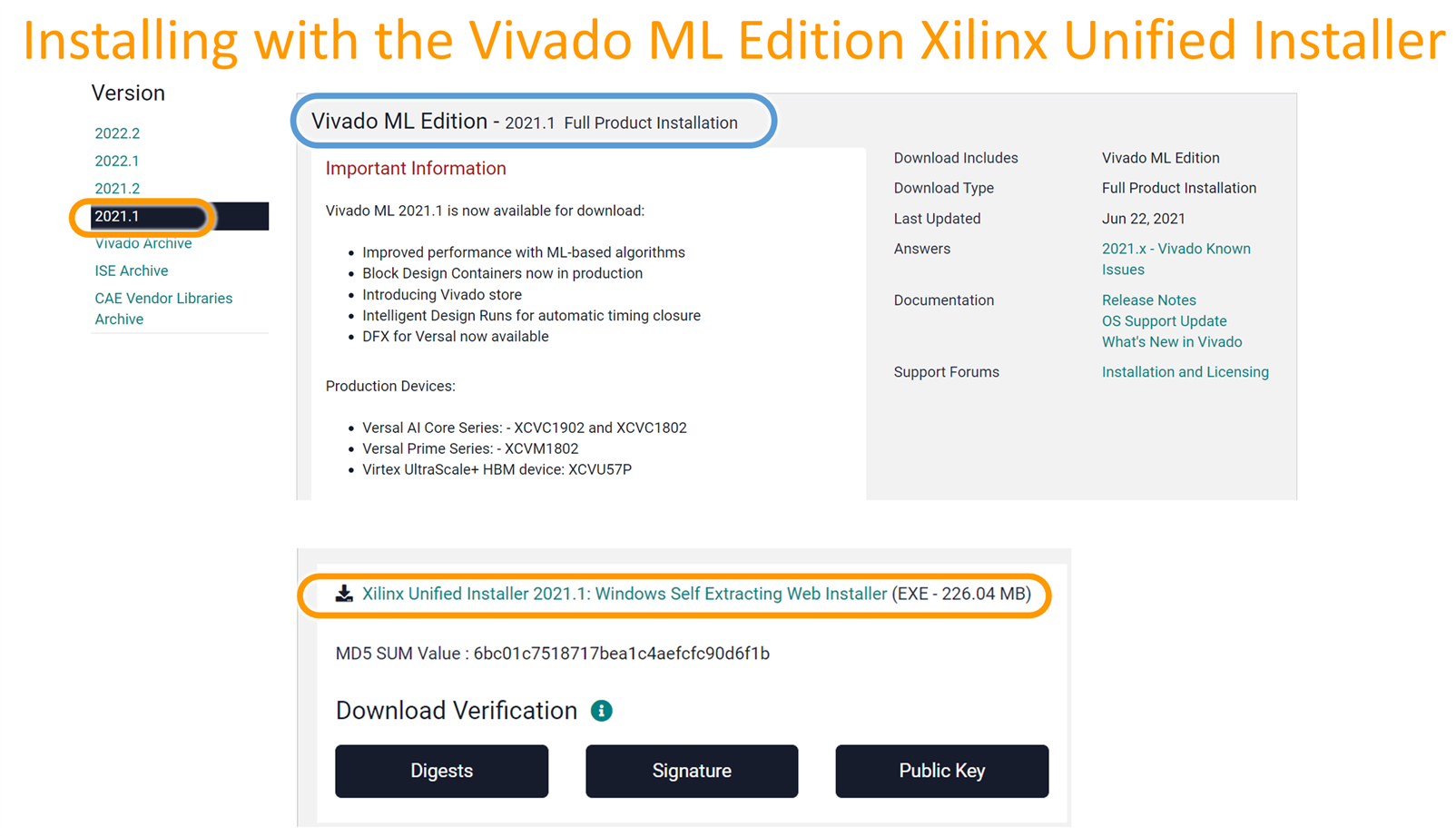
Coming up, I’ll need to get familiar with the development environment. I’ve installed Vivado, and that went fairly smoothly on Windows 10. For those who wish to follow along and develop at the same time, the download that is needed is 2017.4 Vivado HLx WebPack Xilinx Unified Installer for Vivado ML Edition 2021.1.
When the installer is running, you'll be prompted to select the edition to install. Select Vitis Unified Software Platform, becuase you need both Vitis IDE and Vivado to be installed. Vitis IDE is used for software coding (for the ARM core inside the Xilinx chip) and Vivado is used for working with Hardware Description Language (HDL) for the FPGA portion of the chip.
That’s it for the first blog – I hope you’ll stick around for the subsequent posts!
Top Comments
-

mconners
-
Cancel
-
Vote Up
+3
Vote Down
-
-
Sign in to reply
-
More
-
Cancel
-

shabaz
in reply to mconners
-
Cancel
-
Vote Up
+1
Vote Down
-
-
Sign in to reply
-
More
-
Cancel
-

mconners
in reply to shabaz
-
Cancel
-
Vote Up
+3
Vote Down
-
-
Sign in to reply
-
More
-
Cancel
-

shabaz
in reply to mconners
-
Cancel
-
Vote Up
+4
Vote Down
-
-
Sign in to reply
-
More
-
Cancel
Comment-

shabaz
in reply to mconners
-
Cancel
-
Vote Up
+4
Vote Down
-
-
Sign in to reply
-
More
-
Cancel
Children