Intro
This project in the Pi-Fest music technology Design Challenge aims to create a MIDI synthesizer based on a Raspberry Pi PICO. The first blog covered the system block diagram and the circuit description. (see the link below)
This blog covers the PCB design using Eagle. The PCB is designed to be less than 10 cm long to keep its price at $0.50. I did need to stand the audio amplifier up to save some real estate, but this is also useful in placing the volume knob on the top surface. This arrangement leaves plenty of room for the three 40 pin sockets and supporting circuitry discussed in the previous blog. I tend to use sockets when first assembling a new PCB design - to make changes and adjustments easier. It also allows testing the board with some components removed. The software would allow MIDI data to arrive on the USB connector, but I wanted to make sure this synthesizer could connect to any MIDI controller, even if it didn't have a USB output. Stereo audio jacks are often used for MIDI, but I stuck with the classic DIN connector.
PCB Layout
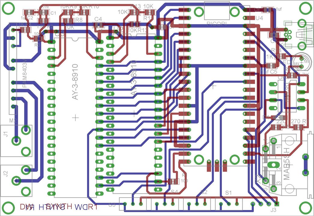
The first step in CAD design is to create all the library parts needed. They need to be meticulously correct and accurate. In this case I had already created all the library parts needed, so the layout went relatively quickly. The second step is to place all the components and decide on board size. I like to place components in such away that I can keep traces short and minimize the number of vias. I even offset the 2 PSG chips to reduce the number of corners in the interconnecting traces.
Here is an image of the 2-layer PCB layout:

I was able to use 0.024" width tracks for all signals and heavier traces for power rails and audio outputs. The layout is very clean with no vias other than those that are part of the the through-hole component footprints. The surface mount components are all 0805 footprints which makes them easy to solder. There is a separate USB connector for power, to reduce the wear and tear on the PICO USB connector and minimize the current flowing through the PICO - to the audio amplifier for example. This USB connector is a through-hole part, to make it much more robust during connector insertion. The PICO itself will automatically handle the situation where both USB connectors have power, even if their voltages are different.
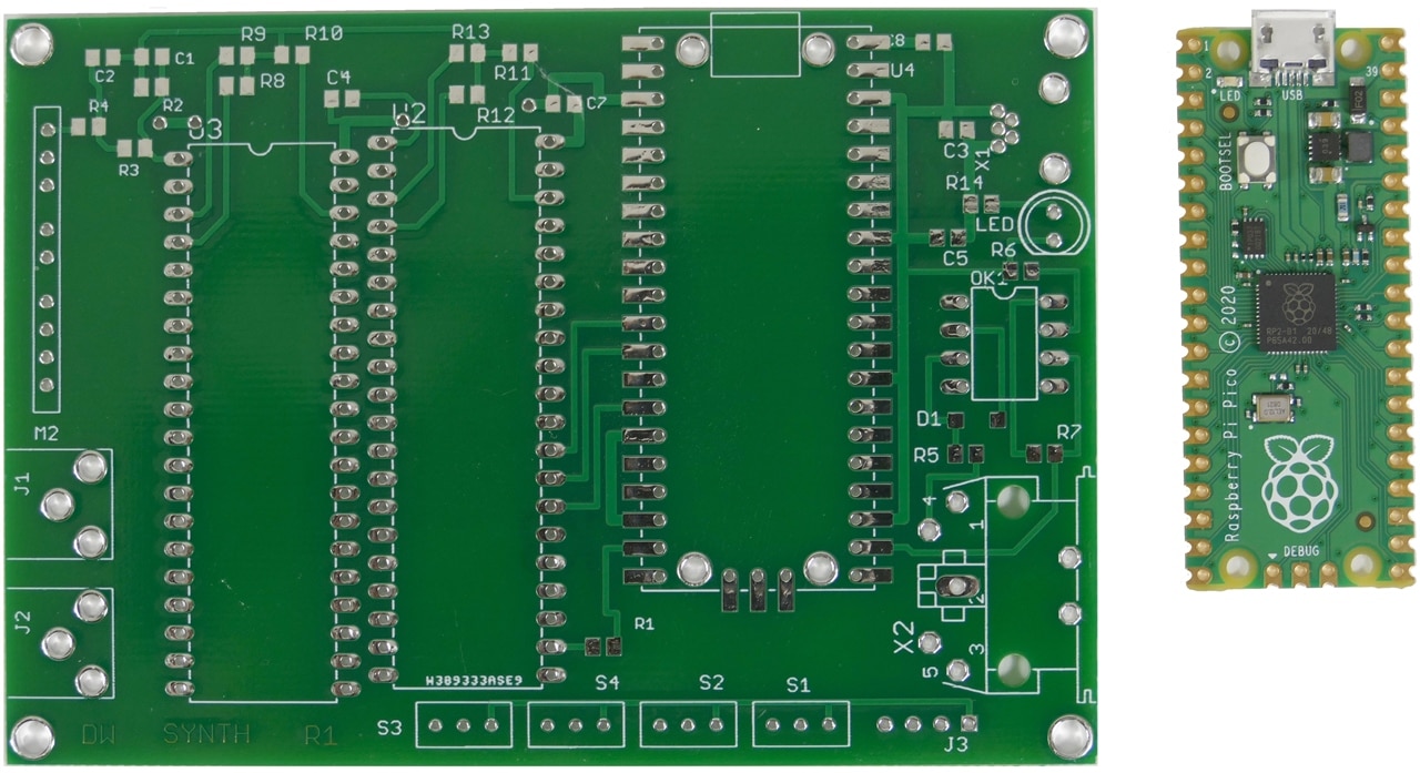
Here is a photo of the bare PCB beside a Pi Pico:

I used PBWay to manufacture the card at a cost of $0.50 per card (for a quantity of 10 cards), so I have extras if I decide to build more synthesizers.
Assembled CCA
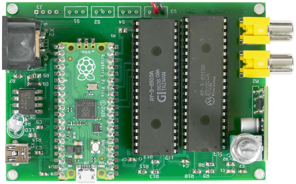
Here is what the synthesizer CCA looks like assembled:

Mystery Melody Medley 2
Here is the second Mystery Melody Medley identification video:
Conclusions and Discussion of this Blog
I Like how this PCB turned out. It is a nice, clean layout that is easy to assemble and even has some extra switches for future expansion.
In the next blog I will publish and discuss the firmware.
Relevant Links:
Blog 1 - Introduction and circuit schematic description
Blog 2 - PCB layout and manufacturing
Blog 3 - Firmware and issues
Blog 4 - Mechanical enclosure design and features
Blog 5 - Project summary and discussion
Pi-Fest Music Contest page
AY-3-8910 Datasheet
Dual Synth link
