


This post should cover how the whole system comes together and how it is controlled.
Previous posts:
Pi IoT - Simone - Introduction
Pi IoT - Simone - #1 - Light Controller
The main system is based on a server application that works on a Raspberry PI. I chose the version 3 for this because it has more connectivity options and more processing power. Mostly there are not many things to process but as the system grows it might be an issue.
This is how the system looks like:
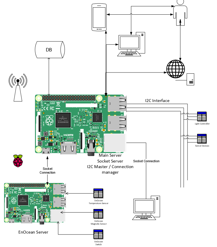
Main Server:
The Raspberry that holds the application for the main server is the most important part since it is the one that ensures the communication between the devices. I started writing the application in C++ since it gives me the possibility to optimize it as much as possible. The server also holds a database where all the necessary data is stored (users, current state of things, reports of usage, etc).
I2C Interface:
At this point the I2C communication is the most used. This can also be reused for other devices that are centralized by another Raspberry, or another device with more processing power than an AtTiny chip. I chose the I2C because it is cheap to use and easily integrated with any other controllers. Here is a good explanation of how I2C works: https://en.wikipedia.org/wiki/I%C2%B2C
The main issue is that there can be only one master on the I2C network and because the micro controllers are not powerful enough I chose to always use the Raspberry as a Master and it pings the devices one by one to see if they have new notifications. When and communication is initialized by the master to a certain device it can also listen for messages sent by it. I made a ping function on the devices that when it is triggered the device responds with the number of notifications that it has. The Master can then ask for them one by one. With the ping function the Master can also know if something happened to a device and it can notify the user.
Another important function is the Identify function. You can see how it responds in the code for the light controller. The idea is that the Raspberry can send an identification message to all available addresses (there are only 127) and if there is an device on that address it can identify itself by saying what type of a device it is and some parameters necessary for the Server to control it.
In the case if the light controller the message was: 1#4#3#Lumini sufragerie#1. The first number is the type if the device. in this case it is defined as switch and the main server knows to make a switch controller base don it. The second parameter is the I2C address of the device. The next ones are particular to the switch devices. The 3 is the number of switches it controls, then there is the name of the switch to be shown to the user (it says "Dining Room Lights"). The last number is an boolean value that states if the switches can be controlled or not.
An issue I encountered is that the I2C communication does not work well on long distances. I used an LAN Cable which has pairs of two wires twisted together. I paired one signal wire with a ground and this clears the signal a bit. Also, to communicate through a 100 m wire I used an transceiver like this one P82B715TD, which actually amplifies the signal to 35 amps and then lowers it back down. This also raises a cost issue but normally you can communicate with no issues in a room through normal I2C but for communication between rooms I've set up a "parrot" device made of two attiny's connected through SPI.

So the Raspberry server sees in the message an address written on 4 bytes, the first two are for the parrot device and the last two for the actual device.
Here is the functions enum used for implementation, the other functions names are relevant for their functionality:
#ifndef __I2CTYPES_H__
#define __I2CTYPES_H__


enum I2C_FUNCTIONS{
  Ping = 0x01,
  Calibrate = 0x03,
  Identify = 0x05,


  Start = 0x11,
  Stop = 0x13,
  Restart = 0x15,


  Set = 0x21,
  Get = 0x23,
  SetGet = 0x25,


  Execute = 0x31,
  Interrupt = 0x33,


  Send = 0x41,
  SendReceive = 0x43,


  Notify = 0x51,
  GetNotification = 0x53,
  RemoveNotification = 0x54,
  GetAlert = 0x55,
  RemoveAlert = 0x56,


  ResponseConfirmation = 0x61,
  ResendMessage = 0x62,


  Default = 0x00
};


#endif
Socket Connection:
The system has two socket servers.
First server is used to communicate with the user through his devices. All the applications if they are for the phone, PC or web applications have behind them a socket client that can pair with the server through this connection and send/receive data. The server has a interpretation layer that can make the message to be sent to the device, or retrieve information from the database if the device interrogation is not necessary.
Second server is made to communicate with other client applications that are controlled by the server and not by the user. In the diagram it is shown another Raspberry that communicates with the EnOcean devices (I could use only one but I don't have enough pins to plug in the display) and can in turn connect to the main server by this socket server. Another use would be a desktop client that could run some script on your computer when it is triggered. As mentioned before, some control devices can get very complex and then you would need a Raspberry PI behind them and not just an Atmel Chip
(I'm still working on the communication protocol for the clients)
System Communication:
Most of the times the devices that connect through the two socket servers are in the same network. An important thing is to set the IP of the main server as static, and then it can be recognized by the clients. To use the device from outside the network (very important feature this system) you can set up a free host that points to your IP address and foreword the communication port for the User Socket Server to the raspberry PI from your router. Here is one example on how to do it but if I have time I will write one myself for this project: https://www.raspberrypi.org/forums/viewtopic.php?f=36&t=32830
Let me know in the comments of possible issues or if something is not covered enough. Thank you!
<I will attach some code soon, still fixing some issues>
Top Comments