element14 Community
element14 Community
    Register Log In
  • Site
  • Search
  • Log In Register
  • About Us
  • Community Hub
    Community Hub
    • What's New on element14
    • Feedback and Support
    • Benefits of Membership
    • Personal Blogs
    • Members Area
    • Achievement Levels
  • Learn
    Learn
    • Ask an Expert
    • eBooks
    • element14 presents
    • Learning Center
    • Tech Spotlight
    • STEM Academy
    • Webinars, Training and Events
    • Learning Groups
  • Technologies
    Technologies
    • 3D Printing
    • FPGA
    • Industrial Automation
    • Internet of Things
    • Power & Energy
    • Sensors
    • Technology Groups
  • Challenges & Projects
    Challenges & Projects
    • Design Challenges
    • element14 presents Projects
    • Project14
    • Arduino Projects
    • Raspberry Pi Projects
    • Project Groups
  • Products
    Products
    • Arduino
    • Avnet Boards Community
    • Dev Tools
    • Manufacturers
    • Multicomp Pro
    • Product Groups
    • Raspberry Pi
    • RoadTests & Reviews
  • Store
    Store
    • Visit Your Store
    • Choose another store...
      • Europe
      •  Austria (German)
      •  Belgium (Dutch, French)
      •  Bulgaria (Bulgarian)
      •  Czech Republic (Czech)
      •  Denmark (Danish)
      •  Estonia (Estonian)
      •  Finland (Finnish)
      •  France (French)
      •  Germany (German)
      •  Hungary (Hungarian)
      •  Ireland
      •  Israel
      •  Italy (Italian)
      •  Latvia (Latvian)
      •  
      •  Lithuania (Lithuanian)
      •  Netherlands (Dutch)
      •  Norway (Norwegian)
      •  Poland (Polish)
      •  Portugal (Portuguese)
      •  Romania (Romanian)
      •  Russia (Russian)
      •  Slovakia (Slovak)
      •  Slovenia (Slovenian)
      •  Spain (Spanish)
      •  Sweden (Swedish)
      •  Switzerland(German, French)
      •  Turkey (Turkish)
      •  United Kingdom
      • Asia Pacific
      •  Australia
      •  China
      •  Hong Kong
      •  India
      •  Korea (Korean)
      •  Malaysia
      •  New Zealand
      •  Philippines
      •  Singapore
      •  Taiwan
      •  Thailand (Thai)
      • Americas
      •  Brazil (Portuguese)
      •  Canada
      •  Mexico (Spanish)
      •  United States
      Can't find the country/region you're looking for? Visit our export site or find a local distributor.
  • Translate
  • Profile
  • Settings
Pi IoT
  • Challenges & Projects
  • Design Challenges
  • Pi IoT
  • More
  • Cancel
Pi IoT
Blog PiIoT - The perfect reading place #19 [tech]: Dynamic surface, design and simulation
  • Blog
  • Forum
  • Documents
  • Polls
  • Files
  • Events
  • Mentions
  • Sub-Groups
  • Tags
  • More
  • Cancel
  • New
  • Share
  • More
  • Cancel
Group Actions
  • Group RSS
  • More
  • Cancel
Engagement
  • Author Author: balearicdynamics
  • Date Created: 22 Aug 2016 1:11 PM Date Created
  • Views 1728 views
  • Likes 9 likes
  • Comments 6 comments
  • physical pixels
  • internet of things
  • stepper controller
  • robotics
  • dynamic surface
  • piiot
  • gearbest.com
  • 3D Printing
  • muzieum
  • stepper motor
  • motion
  • psoc 4200 family
  • modular element
  • lorenzo merlo
  • iot
  • moving surface
Related
Recommended

PiIoT - The perfect reading place #19 [tech]: Dynamic surface, design and simulation

balearicdynamics
balearicdynamics
22 Aug 2016

Introduction

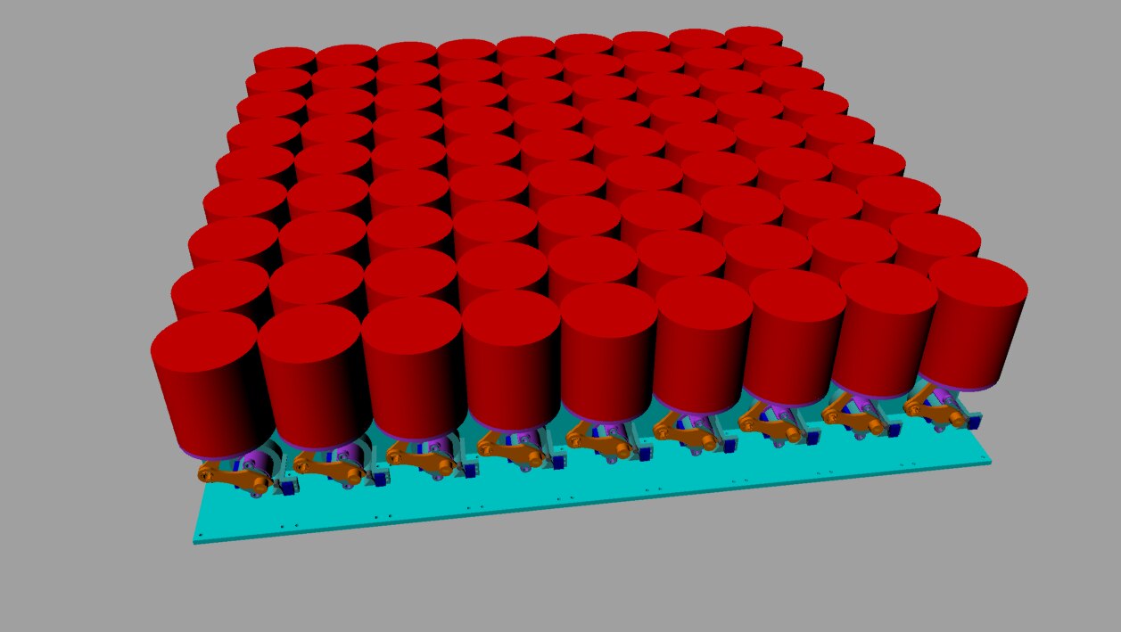
Dynamic surface is another moving subproject part of the PiIot design. It represents an independent moving platform: as well as the PiSense HATPiSense HAT includes an 8x8 RGB LED matrix the Dynamic surface is a physical 8x8 matrix built with big moving pixels. The video below shows a rendered simulation of the assembly design an example of a modular Dynamic Surface built with an asset of 81 modules.


You don't have permission to edit metadata of this video.
Edit media
x
image
Upload Preview
image


Design of the parts

image

As shown above the moving pixel is built of ten pieces to build a m-Pix. A single m-Pix should be self-contained to be assembled in a matrix platform without empty spaces creating the floating surface effect. The rendering of the matrix simulation is shown in the image below.

image

Design requisites

Every module should adhere to the following requisites:

  • Self-contained: Modules should be placed side by side in rows so the mechanics and the motors should be not greater than the m-Pix diameter (8 centimetres)
  • LIghtweight: The moving cylinder should be as light as possible to reduce the effort on the motor and the global weight of the structure
  • Compact and robust: This is mostly a problem of the right choice of the 3D printing structure as the influencing parameter if the solid fill percentage
  • Easy to wire: The modules should make easy the motors wiring row by row, column by column
  • Easy to assemble: The module parts should be easy to assemble also when a considerable number of units will be used
  • Self-positioning: Every module should have a end-stop switch to identify the lower point when the platform is powered or reset.


Designing the assembly sequence

As I wrote many other times before in my opinion the most important step when creating a 3D printer object is the design. I mean that - especially when moving parts are involved -  it is in the design phase that we may create the right solution always considering limits and advantages of the 3D printer technology. The sequence of images below shows the simulation of the parts concurring to make the entire m-Pix module:

image

Image above: the motor and the base support (here in the horizontal view) act on the cylinder while the stabilisation support is internal: this saves a lot of space but grant a good stability to the moving element.

imageimage

image

Above images: Making the moving cylinder in three separate parts saved a lot of time making the things easier. With the stabilisation support built-in the moving component, the cylinder will be the largest element in the module. That is just what we want.


The linear motion transducer

Another important part of the design is how we convert the stepper motor rotation to linear movement:

imageimage

imageimage

As shown in the exploded rendering above the adopted solution is a lever system working as a camshaft. Due the reduced space and the low power her we are using a geared stepper motor that has the disadvantage to move relatively slow than the traditional more powerful steppers. Indeed there are many advantages adopting these devices: reduced size, low power consumption, good Kg/cm rotational force (thanks to the geared engine) and a good positioning precision. For our solution we don't need strong force but the movement should be fluid and a bit higher than the max rotation speed of the motor shaft. This is the reason that the use of the camshaft-like lever multiply a bit the speed conversion.


Providing an easy wiring method

imageimage

Look at the images above. The rendered matrix simulation of some rows of modules shows how the motors wires can be connected to the respective motor controllers. The controllers and the PSoC 4200 array can easily fit on one side of the assembled platform.

The modular matrix can be replicated in multiple ones connected together without difficulty. Now we are ready to make the first prototype to see it in the reality!

  • Sign in to reply

Top Comments

  • shabaz
    shabaz over 9 years ago +2
    Hi Enrico, That's some impressive work, and great video. And an extremely ideal task for 3D printing since it needs to be replicated 64 times! Looking forward to seeing it : )
  • balearicdynamics
    balearicdynamics over 9 years ago in reply to shabaz +1
    Hi friend! Just wait some hours and you'll see. Not only but you should be mentioned too, for a more than valid reason. Enrico
  • DAB
    DAB over 9 years ago +1
    Very nice post and example of how to make physical devices interface with electrical connections. Well done. DAB
  • phoenixcomm
    phoenixcomm over 3 years ago

    impressive!

    • Cancel
    • Vote Up 0 Vote Down
    • Sign in to reply
    • More
    • Cancel
  • volly
    volly over 9 years ago

    balearicdynamics, impressive work....salute!

    • Cancel
    • Vote Up +1 Vote Down
    • Sign in to reply
    • More
    • Cancel
  • balearicdynamics
    balearicdynamics over 9 years ago in reply to DAB

    Thank you DAB. you too, please be patient again few minutes and read the next post image


    Enrico

    • Cancel
    • Vote Up 0 Vote Down
    • Sign in to reply
    • More
    • Cancel
  • DAB
    DAB over 9 years ago

    Very nice post and example of how to make physical devices interface with electrical connections.


    Well done.


    DAB

    • Cancel
    • Vote Up +1 Vote Down
    • Sign in to reply
    • More
    • Cancel
  • balearicdynamics
    balearicdynamics over 9 years ago in reply to shabaz

    Hi friend!


    Just wait some hours and you'll see. Not only but you should be mentioned too, for a more than valid reason.


    Enrico

    • Cancel
    • Vote Up +1 Vote Down
    • Sign in to reply
    • More
    • Cancel
>
element14 Community

element14 is the first online community specifically for engineers. Connect with your peers and get expert answers to your questions.

  • Members
  • Learn
  • Technologies
  • Challenges & Projects
  • Products
  • Store
  • About Us
  • Feedback & Support
  • FAQs
  • Terms of Use
  • Privacy Policy
  • Legal and Copyright Notices
  • Sitemap
  • Cookies

An Avnet Company © 2025 Premier Farnell Limited. All Rights Reserved.

Premier Farnell Ltd, registered in England and Wales (no 00876412), registered office: Farnell House, Forge Lane, Leeds LS12 2NE.

ICP 备案号 10220084.

Follow element14

  • X
  • Facebook
  • linkedin
  • YouTube