element14 Community
element14 Community
    Register Log In
  • Site
  • Search
  • Log In Register
  • Community Hub
    Community Hub
    • What's New on element14
    • Feedback and Support
    • Benefits of Membership
    • Personal Blogs
    • Members Area
    • Achievement Levels
  • Learn
    Learn
    • Ask an Expert
    • eBooks
    • element14 presents
    • Learning Center
    • Tech Spotlight
    • STEM Academy
    • Webinars, Training and Events
    • Learning Groups
  • Technologies
    Technologies
    • 3D Printing
    • FPGA
    • Industrial Automation
    • Internet of Things
    • Power & Energy
    • Sensors
    • Technology Groups
  • Challenges & Projects
    Challenges & Projects
    • Design Challenges
    • element14 presents Projects
    • Project14
    • Arduino Projects
    • Raspberry Pi Projects
    • Project Groups
  • Products
    Products
    • Arduino
    • Avnet & Tria Boards Community
    • Dev Tools
    • Manufacturers
    • Multicomp Pro
    • Product Groups
    • Raspberry Pi
    • RoadTests & Reviews
  • About Us
  • Store
    Store
    • Visit Your Store
    • Choose another store...
      • Europe
      •  Austria (German)
      •  Belgium (Dutch, French)
      •  Bulgaria (Bulgarian)
      •  Czech Republic (Czech)
      •  Denmark (Danish)
      •  Estonia (Estonian)
      •  Finland (Finnish)
      •  France (French)
      •  Germany (German)
      •  Hungary (Hungarian)
      •  Ireland
      •  Israel
      •  Italy (Italian)
      •  Latvia (Latvian)
      •  
      •  Lithuania (Lithuanian)
      •  Netherlands (Dutch)
      •  Norway (Norwegian)
      •  Poland (Polish)
      •  Portugal (Portuguese)
      •  Romania (Romanian)
      •  Russia (Russian)
      •  Slovakia (Slovak)
      •  Slovenia (Slovenian)
      •  Spain (Spanish)
      •  Sweden (Swedish)
      •  Switzerland(German, French)
      •  Turkey (Turkish)
      •  United Kingdom
      • Asia Pacific
      •  Australia
      •  China
      •  Hong Kong
      •  India
      • Japan
      •  Korea (Korean)
      •  Malaysia
      •  New Zealand
      •  Philippines
      •  Singapore
      •  Taiwan
      •  Thailand (Thai)
      • Vietnam
      • Americas
      •  Brazil (Portuguese)
      •  Canada
      •  Mexico (Spanish)
      •  United States
      Can't find the country/region you're looking for? Visit our export site or find a local distributor.
  • Translate
  • Profile
  • Settings
Pi IoT
  • Challenges & Projects
  • Design Challenges
  • Pi IoT
  • More
  • Cancel
Pi IoT
Blog PiIoT - The perfect reading place #7 [tech]: Art-a-tronic, mechanic design
  • Blog
  • Forum
  • Documents
  • Polls
  • Files
  • Events
  • Mentions
  • Sub-Groups
  • Tags
  • More
  • Cancel
  • New
  • Share
  • More
  • Cancel
Group Actions
  • Group RSS
  • More
  • Cancel
Engagement
  • Author Author: balearicdynamics
  • Date Created: 11 Jul 2016 5:47 AM Date Created
  • Views 479 views
  • Likes 6 likes
  • Comments 1 comment
  • image processing
  • micro controller
  • visitor
  • photoshop
  • seeing
  • blind
  • adaption
  • piiot
  • visual impaired
  • visual disability
  • enocean
  • nijmegen
  • muzieum
  • stepper motor
  • museum
  • challenge
  • gearbest
  • lorenzo merlo
  • iot
  • piiot challenge
  • netherland
  • motor controller
  • interaction
  • psoc
Related
Recommended

PiIoT - The perfect reading place #7 [tech]: Art-a-tronic, mechanic design

balearicdynamics
balearicdynamics
11 Jul 2016

Reminder

The mechanic design and many of the motion solutions adopted and experimented in this part of the project will be reused creating the Dynamic Surface as mentioned in PiIoT - The perfect reading place #5 [doc]: Architecture and design


About the moving parts

To increase the perception of the image a flat design should be transformed in a solid object where some image elements (hairs, eyes, lips, nose) react to the human interaction: hairs, nose, lips and eyes extrude at different heights with an excursion of 5-10mm. To reach this goal the back side of the Art-a-tronic will include motors, motor controllers and a micro controller activating the animation when a presence is detected nearby the opera through an ultrasonic sensor and touch enabling via cap sensing some areas nearby the installation.


Hardware components

The moving mechanism is conditioned by the adopted hardware. The parts involved in this model will be the following:

image

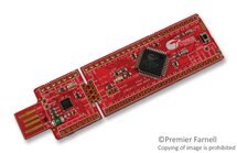
Cypress CY8CKIT-049-42XX

The micro controller will manage the stepper motors as a direct feedback from an ultrasonic sensor.

As the Art-a-tronic is a IoT node it will interact with the enOcean wireless network.


image

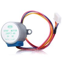
5V geared micro stepper motor provided by GearBest


image

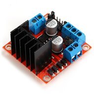
Stepper motor controller based on L298 provided by GearBest


Making the parts moving

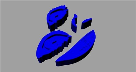
The 3D design of the moving parts has been created by steps explained below with a series of rendered images. The final Art-a-tronic is moved by seven stepper motors.
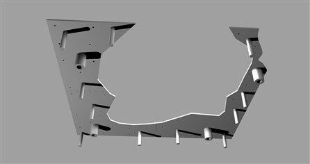
 

Building the base

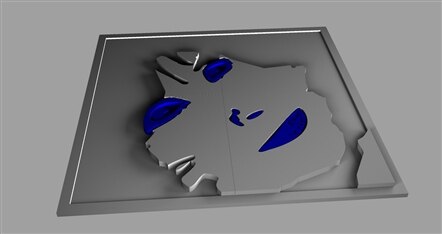
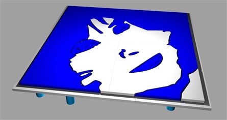
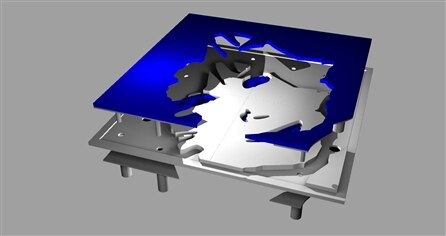
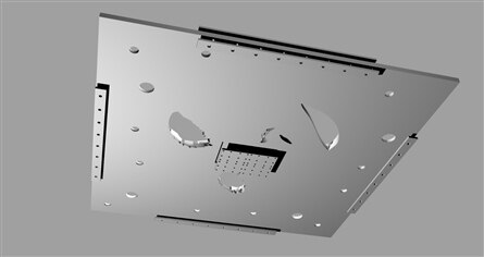
The white base covers two roles: it is the visible support of the Art-a-tronic including the fixed parts (the white background n the flat image). When in standby the moving blue components should appear at the same level so the white visible parts are extruded.

imageimage

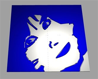
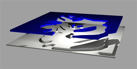
As shown in the above images the base (white) contour has been reduced a while to permit the up-down (blue) movement.

The base is also the support of the entire structure; an external border is provided to make a frame helping to assemble the four parts in a single solid element. To slide vertically the moving objects we should include a support plane moved from the bottom by the stepper motors. This requires and extra 2mm engraving in the base (white) to host the support surface.

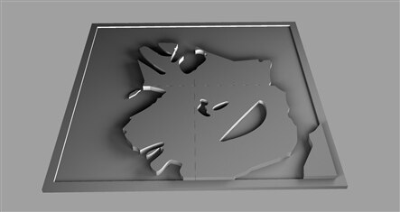
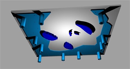
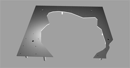
The images below shows the rendered base model.

imageimage

imageimage


Supporting the moving parts

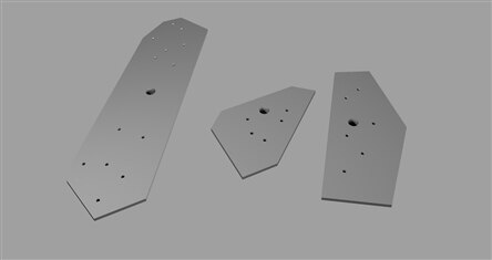
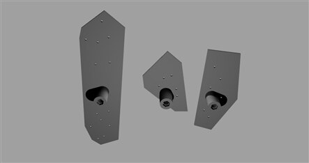
When the moving elements (blue) are pushed up outside the base should be kept in place. The top moving components are assembled over their respective top supports hosting the motor screwed shaft and three stabilisation pins for every element. The base is enforced by a bottom support including a hole for every motor shaft and three pipe-guides for the stabilisation pins.

imageimage

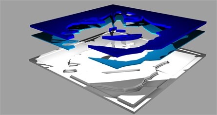
Top and bottom pre-assembled rendering

imageimage

Top and bottom rendering of the top supports

imageimage

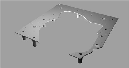
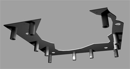
Top and bottom rendering of the bottom supports


Adding the assembly elements

Due the 3D printer limits - the max printable area is few less than 200x200 mm - every part is built with four separate elements. Thus we should add extra-components to keep together the final structure.

Two supports (top and bottom) has been added to every side of the frame and a rectangular support complete the final building to the bottom center of the ideal cross separating the four sectors.

imageimage


Moving eyes, nose and lips

The four parts of the (blue) hairs lays on the (white) base but the remaining three parts (requiring other three motors) follows the opposite logic: eyes, nose and lips are pushed from the bottom emerging from the base holes. These parts are self-guided inside the base.

imageimage

In the eyes, nose and lips the top supports have been removed so the components height includes the thickness of the base layer.
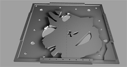
 

Ready for printing

The images below shows all the 3D printable parts of the first 3d designed prototype, top and bottom view.

imageimage

imageimage

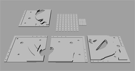
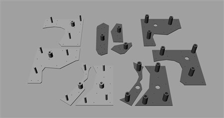
It is needed to complete the assembly of a first set of components to complete the motors and electronic parts setup.


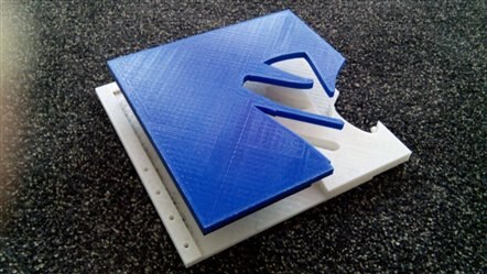
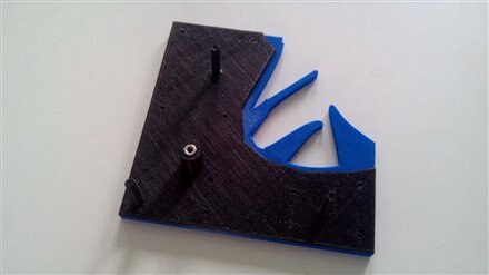
3D print test and minor issues

A first group of test parts has been printed and things sounds good. Some minor issues will require small changes then the final parts can be finally created:


  • Include a small support area to the top and bottom supports for better stability
  • Increase the support pins diameter for more robustness
  • Remove the support holes. The parts will be assembled with super-strong PVC and PLA glue already tested for reliability. This will significantly reduce the weight of the moving parts.
  • Replace the M4 nut for the screwed motors shaft with a tubular M4 support


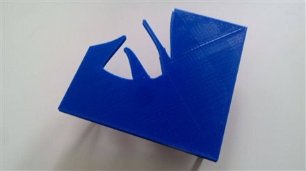
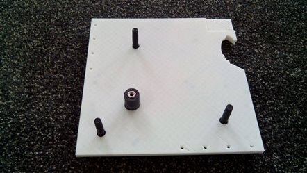
The following images shows the 3D printed parts used for testing

imageimage

imageimage

  • Sign in to reply

Top Comments

  • balearicdynamics
    balearicdynamics over 9 years ago +1
    Update the first series of pieces (white base and blue moving components) has been completed. Below an image.
  • balearicdynamics
    balearicdynamics over 9 years ago

    Update


    the first series of pieces (white base and blue moving components) has been completed. Below an image.


    image

    • Cancel
    • Vote Up +1 Vote Down
    • Sign in to reply
    • More
    • Cancel
element14 Community

element14 is the first online community specifically for engineers. Connect with your peers and get expert answers to your questions.

  • Members
  • Learn
  • Technologies
  • Challenges & Projects
  • Products
  • Store
  • About Us
  • Feedback & Support
  • FAQs
  • Terms of Use
  • Privacy Policy
  • Legal and Copyright Notices
  • Sitemap
  • Cookies

An Avnet Company © 2025 Premier Farnell Limited. All Rights Reserved.

Premier Farnell Ltd, registered in England and Wales (no 00876412), registered office: Farnell House, Forge Lane, Leeds LS12 2NE.

ICP 备案号 10220084.

Follow element14

  • X
  • Facebook
  • linkedin
  • YouTube