


The PiCassoTizer project is one of those projects where you attempt something completely different without any assurance of success, but you know it is going to at least be a fun learning experience.
Applying technology to art sounds risky for someone who is not an artist, so I set out to make a technical tool that would allow art to be created. Regardless of the quality of the art, the tool could be used to create art at whatever level the artist can muster.
The system was developed in stages to try and get subsystems working that I had never tried before:
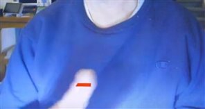
- I had never attempted to do any kind of image processing with a Raspberry Pi, so connecting a camera and performing finger or pointer recognition on captured images was a whole new experience for me. That aspect of the project turned out very well. There were some useful examples on the web that helped get the basics working.
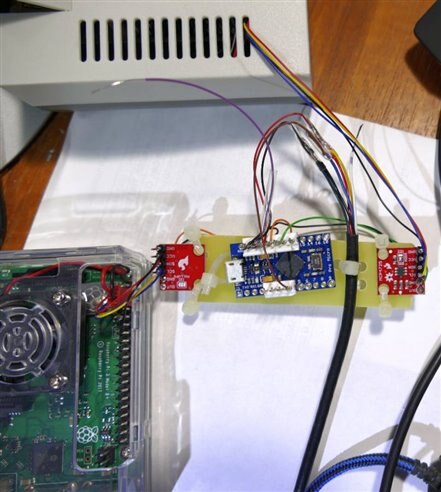
- I had never used I2C with a Raspberry Pi, but again there were some relevant examples on the web that helped get started with sending data to an I2C DAC. The DAC creates an analog output corresponding to finger position in the camera field of view. After problems obtaining some DACs, this part of the project turned out fully successful.
- I had never figured out how to send absolute mouse HID position commands before, and there were differences in operation on a Raspberry Pi versus a PC, but I built an X-Y slide pot arduino mouse to help troubleshoot this part of the project and eventually got good absolute control of mouse position, which was crucial in allowing the finger position to dictate mouse position:

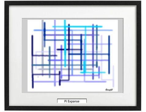
This X-Y slide controller worked so well, and was so unique, I used it to create several pieces of art:

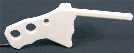
- In order to enable precise drawing control, I designed a 3D printed pointer that could be used instead of a finger. I added mouse buttons to the pointer so that full mouse control would be available in one device. To provide even better control I added a 100% debounce circuit to the mouse buttons, which provided ultra responsive buttons with no undesired extra button pushes from switch bounces.
All the subsystems worked very well, but this provided a false impression that putting the whole system together would be easy and work well.
- The first issue I ran into was translating the coordinate transformation and trigonometric calculations into code would be easy. For some reason, it is much easier to make a mistake when writing a long equation in a line of code that it is when writing it on a piece of paper. I did finally get it all sorted out, but I am going to remember this lesson.
- Another issue that I was not expecting was wiring up the simple debounce circuit - I made several mistakes and had to rework the wiring several times. I didn't damage anything, but after designing a nice long string of PCBs with no errors, it was pretty embarrassing to make so many trivial mistakes in manual wiring. Maybe next time I will just make a PCB - it would be much smaller.

- a fairly major issue I had was underestimating how much infrastructure I would need to bring up the full system. The system needed 5 computers which in turn needed 4 keyboards, 4 mice and at least 4 displays, and they all needed to be worked on essentially at the same time. I was barely able to manage all this and I had to constantly switch which display was connected to which computer. The only way I could manage it was to use my PC "desk" and displays which are not well set up for lighting and blogging.

- The full system ran into noise issues and there wasn't enough time to really sort them out. Part of the problem was the old webcams I had to use - one of them was much worse than the other and since the system needed both, the overall result was dictated by the worst performer.
- I had significant problems with receiving parts I ordered. (not the fault of element14)
- The DACs never arrived and I had to find a second source at considerable cost increase. This delayed the project.
- The webcams never arrived. This was a huge issue that really degraded the final result of the project. It adversely affected the schedule, the geometry, the aesthetics and the performance. When it looked like they just wouldn't ever get here, I tried to buy webcams locally and was surprised that all the usual stores where you would expect to find webcams had no stock. I guess there isn't much of a market for them anymore.
- I discovered that not all Raspberry Pi cases are created equal. I wanted to have a fan in the case and only one of the cases I collected came with a fan. Fortunately I had purchased a selection of fans earlier to deal with this type of requirement, and I actually had enough fans that fit the specific cases. However 2 of the fans are annoyingly loud.
- The case that worked the best for this project was the clear case that came as part of the challenge kit. The fan I found for it was pretty quiet, although it is still audible. The opening to access the expansion connector was perfect.
- The aluminum case I got looked great, but the holes didn't line up perfectly - I had to ream one of them and the fan cover is pushing on the SD card. There is a slot to get wires into the expansion connector, but it is a pretty convoluted path and it would be hard to maintain reasonable aesthetics.
- The Nintendo style case I got was cute, but it only had tiny self-tapping screws to hold it together. It had to be taken apart a few times to run wires as there was no real access to the expansion connector, and this was very risky with such small screw purchase.
What would I do differently next time?
- I think I would use PiCams maybe the PiCam Noir with IR lighting. The reason I didn't use them initially was because they have a narrow field of view, but I now think I could work around that issue. They have an advantage in having lower latency than webcams, which would make the system much more responsive.
- I might try to avoid DACs and make the arduino into a slave I2C device, although the reason I didn't try this the first time was I couldn't find a good example - it would need to be a slave to two masters.
Summary
This project was lots of fun. Getting all the subsystems working involved learning new things and provided lots of satisfaction when they were successful.
I got to design some electronics, design some mechanical parts, design some software, make some systems work, create some art, and interact with forum members.
That is precisely what I wanted from this project.
Oh, and I scored a nice kit of parts from element14 to help implement the design … and there was a very nice finisher prize as well - pictured in the comments below....
I am happy to have had the opportunity to participate in this different type of design challenge.
Thanks element14 and all the members who tuned in to watch or comment on the work.
Relevant links:
PiCassoTizer - Introduction - blog 1
PiCassoTizer - Electronic Parts - Blog 2
PiCassoTizer - Finger Detection Image Processing - Blog 3
PiCassoTizer - Absolute Mouse Position - HID Simulation - Blog 4
PiCassoTizer - The Snowman Smiles - Blog 5
PiCassoTizer - Pi Expanse - blog 6
PiCassoTizer - The Wand - Blog 7
PiCassoTizer - The DAC - Blog 8
PiCassoTizer - Electronics Functional Test - Blog 9
PiCassoTizer - The Journey - Blog 10
Finisher Prize
Top Comments