element14 Community
element14 Community
    Register Log In
  • Site
  • Search
  • Log In Register
  • Community Hub
    Community Hub
    • What's New on element14
    • Feedback and Support
    • Benefits of Membership
    • Personal Blogs
    • Members Area
    • Achievement Levels
  • Learn
    Learn
    • Ask an Expert
    • eBooks
    • element14 presents
    • Learning Center
    • Tech Spotlight
    • STEM Academy
    • Webinars, Training and Events
    • Learning Groups
  • Technologies
    Technologies
    • 3D Printing
    • FPGA
    • Industrial Automation
    • Internet of Things
    • Power & Energy
    • Sensors
    • Technology Groups
  • Challenges & Projects
    Challenges & Projects
    • Design Challenges
    • element14 presents Projects
    • Project14
    • Arduino Projects
    • Raspberry Pi Projects
    • Project Groups
  • Products
    Products
    • Arduino
    • Avnet & Tria Boards Community
    • Dev Tools
    • Manufacturers
    • Multicomp Pro
    • Product Groups
    • Raspberry Pi
    • RoadTests & Reviews
  • About Us
  • Store
    Store
    • Visit Your Store
    • Choose another store...
      • Europe
      •  Austria (German)
      •  Belgium (Dutch, French)
      •  Bulgaria (Bulgarian)
      •  Czech Republic (Czech)
      •  Denmark (Danish)
      •  Estonia (Estonian)
      •  Finland (Finnish)
      •  France (French)
      •  Germany (German)
      •  Hungary (Hungarian)
      •  Ireland
      •  Israel
      •  Italy (Italian)
      •  Latvia (Latvian)
      •  
      •  Lithuania (Lithuanian)
      •  Netherlands (Dutch)
      •  Norway (Norwegian)
      •  Poland (Polish)
      •  Portugal (Portuguese)
      •  Romania (Romanian)
      •  Russia (Russian)
      •  Slovakia (Slovak)
      •  Slovenia (Slovenian)
      •  Spain (Spanish)
      •  Sweden (Swedish)
      •  Switzerland(German, French)
      •  Turkey (Turkish)
      •  United Kingdom
      • Asia Pacific
      •  Australia
      •  China
      •  Hong Kong
      •  India
      • Japan
      •  Korea (Korean)
      •  Malaysia
      •  New Zealand
      •  Philippines
      •  Singapore
      •  Taiwan
      •  Thailand (Thai)
      • Vietnam
      • Americas
      •  Brazil (Portuguese)
      •  Canada
      •  Mexico (Spanish)
      •  United States
      Can't find the country/region you're looking for? Visit our export site or find a local distributor.
  • Translate
  • Profile
  • Settings
Pi Chef Design Challenge
  • Challenges & Projects
  • Design Challenges
  • Pi Chef Design Challenge
  • More
  • Cancel
Pi Chef Design Challenge
Blog Cracked pepper sir? (Pieces and Bits) Pi Chef Challenge Blog post #9
  • Blog
  • Forum
  • Documents
  • Polls
  • Files
  • Events
  • Mentions
  • Sub-Groups
  • Tags
  • More
  • Cancel
  • New
  • Share
  • More
  • Cancel
Group Actions
  • Group RSS
  • More
  • Cancel
Engagement
  • Author Author: crackedpepper
  • Date Created: 19 Mar 2018 10:37 AM Date Created
  • Views 680 views
  • Likes 8 likes
  • Comments 2 comments
Related
Recommended

Cracked pepper sir? (Pieces and Bits) Pi Chef Challenge Blog post #9

crackedpepper
crackedpepper
19 Mar 2018

So This week I didn't end up getting much time to work on the project. I focused on final testing of the arm and finding an alternative to running the grinder from the Pi Face.


For the final testing of the arm I simply wanted to run both motors at the same time to test the movement of the arm. This was successful but I found the movement to be quite jerky. The circuit I used is pictured below:

image


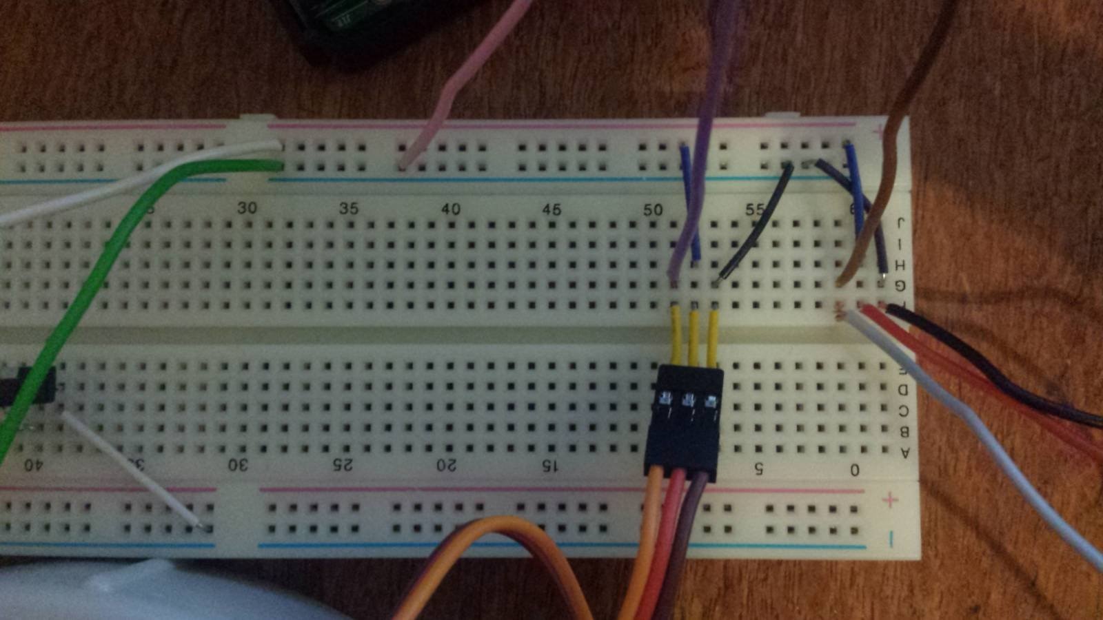
The purple and brown wires run to pins 17 and 27 respectively (BCM numbering), the pink wire runs to the ground on the Pi at pin 39 (Board numbering). The green and white wires run to a 5V 3A power supply. The grey, red, and black wires connect to the second servo in the same configuration as the visible connector (PWM input, positive and negative from left to right).


With the initial testing out of the way i moved onto getting an alternative to the relay on the Pi Face running the grinder. The Pi Face was unsuitable as i dint want to try and solder wires below the header connection, I haven't looked into the schematics in detail but according to this post some are free PiFace Digital 2 - Free GPIO pins? .


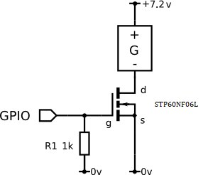
In my 3rd post i mentioned that i bought a mosfet which i tried to use to run the grinder but i didn't have any success I came back to this to give it another try The mosfet I purchased was an  STP60NF06LSTP60NF06L which is probably overkill for this project(the factsheet can be found here). When I initially looked at the fact sheet when ordering I selected this part as the transfer characteristics curve (figure 6 in the previous link) showed that at a gate voltage of 3.3V 40A would flow for a Vgs of 15V. This was much higher than I needed but as long as a gate voltage of 3.3V would be enough I assumed it would work [my lack of electrical engineering knowledge is showing here image]. The circuit I set up is pictured in the diagram below:


image

The physical circuit on the bread board is shown below:

image

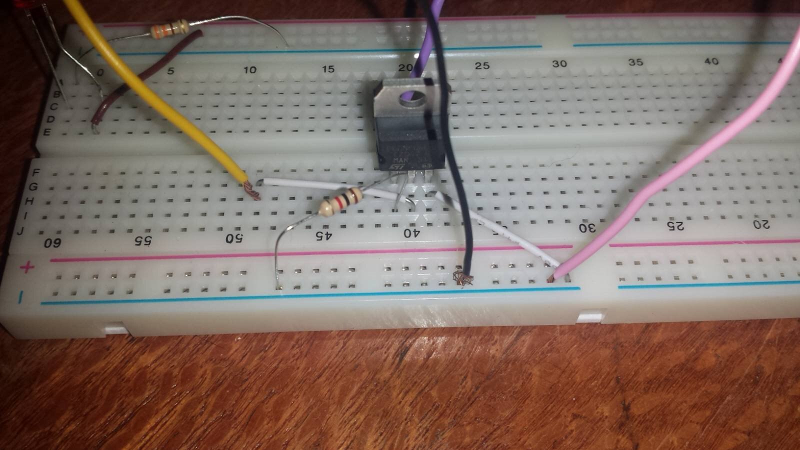
The purple wire connects to the raspberry pi gpio 13(bcm), the pink to the ground on the pi @ pin 39 (board), the yellow to the grinder motor and the black to the negative of the grinders batteries. This worked well and it will be the circut i use in the final build. I'm not actually sure what i did wrong last time I tried to make this circuit but at least i was successful this time.


Next week I aim to connect the final dots and have a complete working prototype image

  • Sign in to reply

Top Comments

  • genebren
    genebren over 7 years ago +1
    Nice update on your project. It is good that you are getting the electronics working. Servos are pretty touchy in direct drive situations. They tend to snap to position quickly on changes in command. I…
  • crackedpepper
    crackedpepper over 7 years ago in reply to genebren +1
    Thanks for the tip, I'll have a look at it this week
  • crackedpepper
    crackedpepper over 7 years ago in reply to genebren

    Thanks for the tip, I'll have a look at it this week

    • Cancel
    • Vote Up +1 Vote Down
    • Sign in to reply
    • More
    • Cancel
  • genebren
    genebren over 7 years ago

    Nice update on your project.  It is good that you are getting the electronics working.  Servos are pretty touchy in direct drive situations.  They tend to snap to position quickly on changes in command.  I have had some success in filtering the servo  command going into the PWM driver with digital filtering.  This way the pulse width is commanded to slowly change, allowing the servos to 'slew' to position instead of 'snapping' to position.

    Good luck on your next steps.

    Gene

    • Cancel
    • Vote Up +1 Vote Down
    • Sign in to reply
    • More
    • Cancel
element14 Community

element14 is the first online community specifically for engineers. Connect with your peers and get expert answers to your questions.

  • Members
  • Learn
  • Technologies
  • Challenges & Projects
  • Products
  • Store
  • About Us
  • Feedback & Support
  • FAQs
  • Terms of Use
  • Privacy Policy
  • Legal and Copyright Notices
  • Sitemap
  • Cookies

An Avnet Company © 2026 Premier Farnell Limited. All Rights Reserved.

Premier Farnell Ltd, registered in England and Wales (no 00876412), registered office: Farnell House, Forge Lane, Leeds LS12 2NE.

ICP 备案号 10220084.

Follow element14

  • X
  • Facebook
  • linkedin
  • YouTube