


Unboxing the Grid-Eye sensor
Last week I received the Grid-Eye sensor. It is a tiny device and looks quite unspectacular

I ordered the version AMG8834AMG8834 It works with 3.3 V which is perfect for interfacing with the Raspberry Pi and is a low gain type This means it can measure temperatures from-20°C to+100°C which should be OK for cooking
Setting up the Hardware
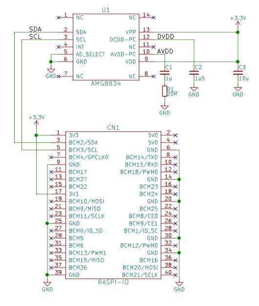
Below you can see a little schematics page I made with KiCad how to connect the sensor to the Raspberry Pi GPIO header. It is quite simple. You just need the 3.3 V from the GPIO header and place a resistor and 3 capacitors along the sensor. Then connect SDA and SCL from the I2C bus and that's it. You don't need any pull-up resistors on SDA and SCL because the Raspberry Pi already has them onboard. And you don't need to connect the INT-line since we won't use the interrupt function of the sensor.
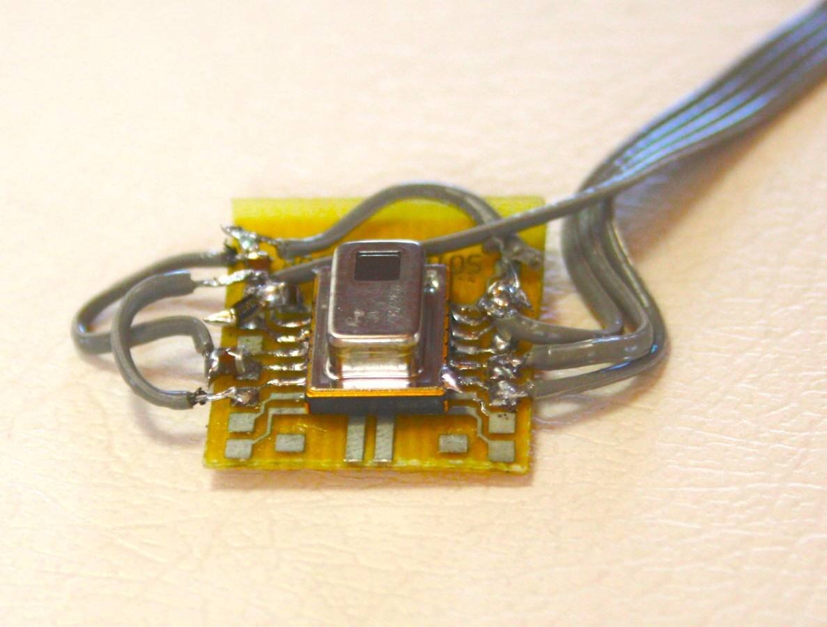
I placed the sensor and the additional parts on a little break out board. It looks a little bit creepy but it is working perfectly.
The software part
Scanning for the sensor
The sensor is connected to the Raspberry Pi via I2C. By default I2C is not enabled on the Raspberry Pi. So you first have to enable it using raspi-config. You find the setting under "Interfacing Options".
After you enabled I2C you can scan the I2C bus with the command i2cdetect -y 1 as on the following screenshot:
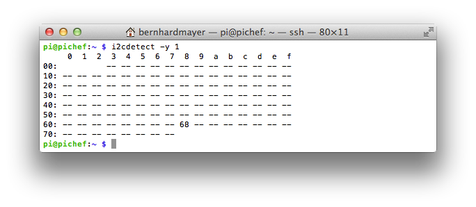
Here a device is detected with the address 0x68. This is the grid-eye sensor. So it seems to be working.
First demo program
Then I wrote a liitle demo programm in C to test and read out the sensor. I am using the libi2c-dev which has to be installed first using the following command:
sudo apt-get install libi2c-dev
The grid-eye sensor has an additional internal temperature sensor (not the sensor array) which I try to read out first as a test. Here is the source code of my program:
#include
#include
#include
#include
#include

int main(void)
{
    int file;
    int addr=0x68;        // adress of AMG88xx
    signed short int internal_temp;

    printf("AMG88xx\n");
    if((file=open("/dev/i2c-1",O_RDWR))<0)    // open i2c-bus
    {
        perror("cannot open i2c-1");
        exit(1);
    }
    if(ioctl(file, I2C_SLAVE, addr)<0)    // open slave
    {
        perror("cannot open slave address");
        exit(1);
    }

    internal_temp=(signed short)(i2c_smbus_read_word_data(file, 0x0e)<<4);    // read out internal temp sensor and cast it to signed short
    internal_temp=internal_temp/16;    // modify value to original value
    printf("Internal Temp: %f C (0x%04X = %i)\n",(float)internal_temp*0.0625,internal_temp,internal_temp);

    close(file);

    return 0;
}
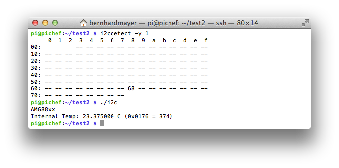
The sensor works quite simple. You don't have to start nor set any initialisation registers. It just works out of the box and you can start reading the registers.
Here is a screenshot of the output of the program:
Reading the sensor array.
The next step is to read out the sensor array. The values of the sensor array are simply mapped on the register range and you can read out one after another. I realized this with a 2 dimensional for loop. Here is the source code:
#include
#include
#include
#include
#include


int main(void)
{
    int file;
    int addr=0x68;        // adress of AMG88xx
    int x,y;        // variables to got through the array
    char register_address=0;    // register_address of each sensor pixel
    signed short int internal_temp;
    signed short int pixel_temp;

    printf("AMG88xx\n");
    if((file=open("/dev/i2c-1",O_RDWR))<0)    // open i2c-bus
    {
        perror("cannot open i2c-1");
        exit(1);
    }
    if(ioctl(file, I2C_SLAVE, addr)<0)    // open slave
    {
        perror("cannot open slave address");
        exit(1);
    }

    internal_temp=(signed short)(i2c_smbus_read_word_data(file, 0x0e)<<4);
    internal_temp=internal_temp/16;
    printf("Internal Temp: %f C (0x%04X = %i)\n",(float)internal_temp*0.0625,internal_temp,internal_temp);

    printf("-------+-------+-------+-------+-------+-------+-------+-------\n");
    for(x=0;x<8;x++)
    {
        for(y=0;y<8;y++)
        {
            register_address=0x80+2*((x*8)+y);
            pixel_temp=(signed short)(i2c_smbus_read_word_data(file, register_address)<<4);  // read pixel_temp and cast to signed short
            pixel_temp=pixel_temp/16;  // set pixel_temp to original value
            printf(" %2.2f ",(float)pixel_temp*0.25);
            if(y<7) printf("|");
        }
        printf("\n");
        printf("-------+-------+-------+-------+-------+-------+-------+-------\n");
    }
    close(file);

    return 0;
}
And here is a screenshot of the output.
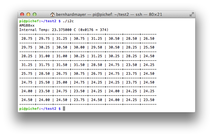
All measured values are in the range between 20 and 30 °C. This seems plausible since I did the measurement in my work room.
The I2C programming could be speed up a little bit if I read multiple registers at once. But this is only a little demonstrator and it works so I leave it as it is for now. Maybe I improve the code during the progress of the project.
Making a nice image with OpenCV
The next step is to use the output of the previous program and feed it into OpenCV and make a nice image. In my last blog post I already explained the setup of a simple OpenCV program. I will reuse much of the code and add the sensor data. I read out the sensor just like in the previous program and store the data in a 8x8 OpenCV-Mat. Then I normalize the data and color it with a predefined color map. This gives you very fast a very nice result.
Here is the source code:
#include
#include
#include
#include
#include
#include
#include
#include


int main(void)
{
    int file;
    int addr=0x68;        // adress of AMG88xx
    int x,y;     // variables to got through the array
    char register_address=0;    // register address of each sensor pixel
    signed short int internal_temp;
    signed short int pixel_temp;

    int end=1;  // variable to end program
    printf("Pi Chef Stove Assistant Demo with AMG88xx\n");  // print start message
    if((file=open("/dev/i2c-1",O_RDWR))<0)    // open i2c-bus
    {
        perror("cannot open i2c-1");
        exit(1);
    }
    if(ioctl(file, I2C_SLAVE, addr)<0)    // open slave
    {
        perror("cannot open slave address");
        exit(1);
    }

    internal_temp=(signed short)(i2c_smbus_read_word_data(file, 0x0e)<<4);
    internal_temp=internal_temp/16;
    printf("Internal Temp: %f C (0x%04X = %i)\n",(float)internal_temp*0.0625,internal_temp,internal_temp);

    cv::Mat inputImage(1024,1280,CV_8UC3);  // create opencv mat

    cv::Mat outSmall(8,8,CV_8UC1);        // create opencv mat for sensor data
    cv::Mat outSmallnorm(8,8,CV_8UC1);    // create opencv mat for normalized data
    cv::Mat outColor;    // create opencv mat for color output

    while(end==1)  // check end variable
    {
        printf("-------+-------+-------+-------+-------+-------+-------+-------\n");
        for(x=0;x<8;x++)
        {
            for(y=0;y<8;y++)
            {
                register_address=0x80+2*((x*8)+y);
                pixel_temp=(signed short)(i2c_smbus_read_word_data(file, register_address)<<4);    // read pixel_temp and cast to signed short
                pixel_temp=pixel_temp/16;    // set pixel_temp to original value
                printf(" %2.2f ",(float)pixel_temp*0.25);
                if(y<7) printf("|");
                outSmall.at(x,y)=pixel_temp;
            }
            printf("\n");
            printf("-------+-------+-------+-------+-------+-------+-------+-------\n");
        }

        cv::normalize(outSmall,outSmallnorm,255,0,cv::NORM_MINMAX);    // normalize Mat to values between 0 and 255
        cv::resize(outSmallnorm,outSmallnorm,cv::Size(256,256));    // resize Mat to 256 x 256 pixel
        cv::applyColorMap(outSmallnorm,outColor,cv::COLORMAP_JET);  // generate colored output with colormap
        cv::imshow("AMG88xx",outColor);  // display mat on screen
        char key = cv::waitKey(500);  // check keys for input
        if(key=='e') end=0;  // end if e was pressed
    }
    printf("ended regularly!\n");  // print end message
    close(file);
    return 0;
}
And here is a screenshot of the output:
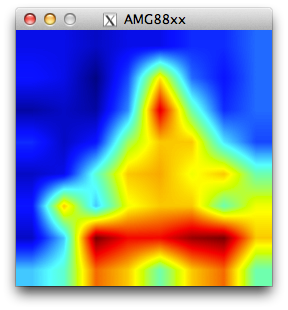
This is me sitting on a chair in front of the grid-eye sensor.
In the program there may be a little bug with the conversion of the short int values of the sensor to the char values of the OpenCV mat but I will have a look on this later.
What's next?
Next week I will mount the grid-eye sensor and the Raspberry Pi camera next to each other on a common plate and see how they align.
Top Comments