


In my last post, I chose some hardware that acquires and measures temperatures. Now that I have a thermistor probe and an ADC, how should I hook them together and interpret the ADC output to get a temperature value? This post explains some theory and my thought process, in three parts.
Part 1: Theory
Voltage Divider
A thermistor is a kind of variable resistor. As the temperature changes, its resistance changes. This resistance is what I have to measure using the Analog-to-Digital Converter (ADC), but an ADC can’t measure resistance directly: it only reads a voltage. Instead, I’ll need to place the thermistor in a circuit in order to produce a voltage that varies according to its resistance. The circuit I’m going to use is called a voltage divider, which is made up of two resistors connected in series, with the output connected between them.
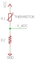
Figure 1. Schematic of a voltage divider
If you know the resistance of one of the resistors and measure the voltage across it, you can calculate the resistance of the other one using this equation:

Figure 2. Voltage divider equation.
In my case, I’m going to use the Raspberry Pi’s 3.3V power pin as VCC, and my thermistor will be R1. I will have to choose a resistor value for R2. The voltage divider circuit will work with any resistor here, but I want to be strategic about my choice. Before I can make that decision, I need to know more about my thermistor.
Thermistors and the Steinhart-Hart Equation
I purchased ThermoWorks Pro Series thermistor probes. These thermistors are Negative Temperature Coefficient (NTC) type, which means that as the temperature increases, the resistance decreases. You can read about how thermistors work on Wikipedia, but the important thing to note is this relationship between temperature and resistance is not linear, so it’s not a simple task to convert the resistance into a temperature value. The relationship is described by the Steinhart-Hart Equation, and it requires three coefficients, A, B, and C, which depend on the material characteristics of the thermistor.

Figure 3. Steinhart-Hart Equation, where T is temperature in Kelvins.
These coefficients aren’t published for the probes I purchased, so I’ll have to do some tests in the kitchen in order to find them. Once I have the coefficients, I can plug them into the equation and start using it. Luckily, Wikipedia has instructions for finding the coefficients for the Steinhart-Hart Equation:

Figure 4. Steinhart-Hart Coefficient system of equations. Source: Wikipedia.
Part 2: Determining Steinhart-Hart Coefficients for a Thermistor
Testing the Thermistor
In order to solve for the three coefficients for the Steinhart-Hart Equation, I need to measure the resistance of the thermistor at known temperatures. I’ll need three data points in order to solve the system of three equations. It’s time for some kitchen science!
I’m going to use a stable room temperature, an ice bath, and a boiling water bath as my data points, and I will use a multimeter to measure the resistance of the thermistor when it is at each temperature. I’ll use my digital thermometer connected to the same probe to confirm these temperatures.
I used a mini TS jack and some alligator clips to connect the thermistor to the multimeter. The jack and alligator clips might add a little resistance to my measurements, but the TS jack is what I will be using in the final product, so this should be included in the measurement anyways. Also, my measurements are all several thousand ohms, so I’m going to consider this error negligible.
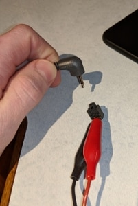
Figure 5. Connecting the probes to the multimeter
The first temperature I used was my ambient room temperature. My digital thermometer said it is 67°F. Next, I connected the probe to my multimeter and recorded its value.
To create the ice bath, I filled a glass full to the top with ice and then poured in distilled water to fill in between the ice chunks. After a minute or so, I gently swirled the probe in the water so that it wasn’t resting against any solid ice and confirmed that it was at 32°F using my digital thermometer. Then, I connected the probe to my meter and recorded its resistance. The number fluctuated a bit depending on how deep the probe was -- the digital thermometer I was using wasn’t capable of distinguishing between these values, so I recorded the highest value I saw, meaning, the lowest temperature that it reached. (This is the suggested calibration method from ThermoWorks, but I don’t feel very confident about this number because of the variance, so I would welcome any suggestions for a better way to do this.)
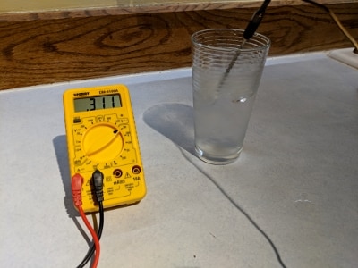
Figure 6. Measuring the temperature of an ice bath. I didn’t manage to get a photo of the actual measurement I used because I took the photo after much of the ice melted.
For the boiling water bath, I dumped the used ice bath into a pot and attached the probe using a pot clip. I added some more water and heated it on the stove until it started to boil. It was interesting to watch the resistance drop on the meter as the water increased in temperature, up until its boiling point. (How does that saying go? “A watched pot never converges to an asymptotically stable temperature?”) Once the water began to boil, I took a few temperature measurements with my digital thermometer and found a heat setting that would cause the temperature to stabilize at 212°F. Then I switched back to the thermistor and recorded the resistance shown on my meter. I’m at basically sea level, so the air pressure shouldn’t cause the boiling point of my water to deviate from 212°F. (32 and 212 are ridiculous numbers. Why am I not using Celsius for everything? Ugh, it’s too late to turn back now.)
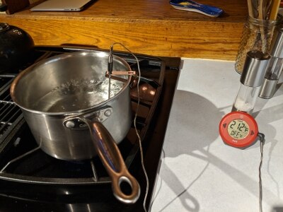
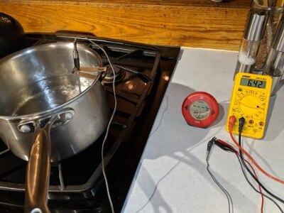
Figure 7. Measuring the temperature of a boiling water bath.
Calculating Steinhart-Hart Coefficients
I finally have the data points I need to find the Steinhart-Hart coefficients. I made a spreadsheet to help me convert Fahrenheit into Kelvin and organize all of the variables. In the end, I came up with the values in Table 1 below.
Table 1. Steinhart-Hart coefficients for my ThermoWorks Pro Series Thermistor probes.
A | 7.62895078820644 x10⁻⁴ |
B | 2.09018336028586 x10⁻⁴ |
C | 1.25383014857396 x10⁻⁷ |
Plugging these values into the Steinhart-Hart Equation gives me this curve:
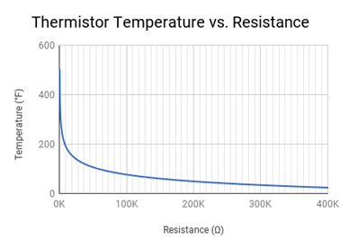
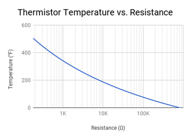
Figure 8. Graphs of temperature vs. resistance for my thermistor probes. The first graph is a linear scale, and the one on the right shows the same data on a log scale.
Part 3: Optimizing the Voltage Divider
ADC Resolution
Now that I have an equation that converts between temperature and resistance, I can finally get around to choosing the other resistor for the voltage divider. My goal here is to find a resistor that gives me the best resolution in the temperature range I’m interested in. In order to make this decision, I want to be able to visualize how the resistance of R2 affects the resolution over the entire temperature range. I’ll need to create another spreadsheet and graph.
At the top of my spreadsheet, I define the constants for my voltage divider circuit, such as VCC and the bit depth of the ADC. It also has a slot for an experimental value of R2, which is what I will be tuning later. In the first column, I have a range of thermistor values for R1. I chose values that kind of follow a log scale (in fact, I used the standard E12 set of resistor values), so my data points aren’t bunched up at the low end. The next column has the temperature at that resistance, calculated using the Steinhart-Hart Equation including the coefficients I found. This will form the X-axis of my graph. The next column computes the expected output voltage of the voltage divider, taking into account the constants of my circuit and the resistance of the thermistor. Then, I calculate the expected ADC value at that voltage in the next column by dividing the voltage by VREF (which I’m setting equal to VCC) and multiplying by the ADC’s range. This predicts the integer value between 0 and 4096 that the Raspberry Pi will receive from the ADC. In the last column, I calculate the average ADC resolution between each row and the row above by dividing the change in ADC value by the change in temperature. Graphing this resolution against temperature gives me the tool I need to choose a value for R2. I also plotted the ADC values on the same graph, which illustrates how it corresponds to resolution.
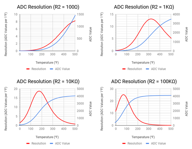
Figure 9. Graphs of temperature vs. ADC resolution at several values of R2.
After trying a few different resistor values as the R2 parameter, I decided to choose R2 = 5.6KΩ. Because I plan to use this with a smoker, I want the best resolution in the low-and-slow cooking range, which is between 200°F and 250°F. 3.3KΩ puts the peak right over this range, but it also means that the resolution drops below 1 at temperatures below about 30°F. Since I may decide to get more probes and measure outdoor air temperature as well, I thought it would be nice to sacrifice a little resolution at 250°F in order to have a little more resolution at the low end. It might be interesting to see how freezing outdoor temperatures affect the cooker.
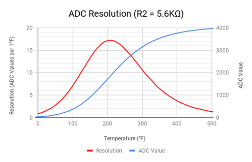
Figure 10. Graph of temperature vs. ADC resolution at my chosen R2 value, 5.6KΩ.
Now that I have chosen my R2 value for my voltage divider and have an equation to convert resistance to temperature, I’m ready to start prototyping! Be sure to check out my next blog post, where I actually hook everything up and get some sensor data!
If you would like to view my thermistor calibration spreadsheet, I have made it public on Google Drive here.
Top Comments