


Contents
01. Rating and Parameters of Polymer Capacitor in the Kits.
First, all the capacitor shall be measured, capacitor measurement with Fluke 106 as comparation. There are some errors with RED text label, it is not clear what the reasons are. Later, I shall figure it out.
Reading A is measured with ESR70 - ESR Meter, Reading B is measured with Fluke 106 multimeter.


02. Simulation of AD8428 Instrumentation Amplifier by ADI
2.1 Simulation with ADIsim
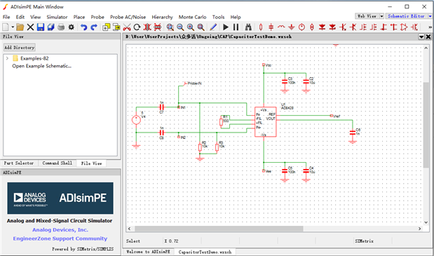
ADIsim is fairly good simulation tools with ample choice and easy configuration. But I can not get expected results when AD8428 is included in the schemetic.
The Instrumentation Amplifier AD8428 is new product, and not included in the out-of-factory library. AD8428 can be imported as third-party lib with officiall SPICE file. It fails again and again. That is not big deal if there is free time to research. SPICE file is in TXT format. But that part have to be saved for later.


2.2 LTspice
LTspice by Linear (sub brand aquired by ADI) is easy to use and fully compatible with ADI products.
2.2.1 Normal Schematic Design on Official Guide
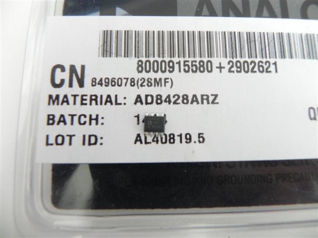
AD8428 Free sample supplied by ADI

According to official manual of AD8428, the following reference design shall be applied.

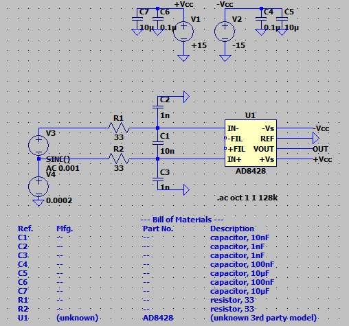
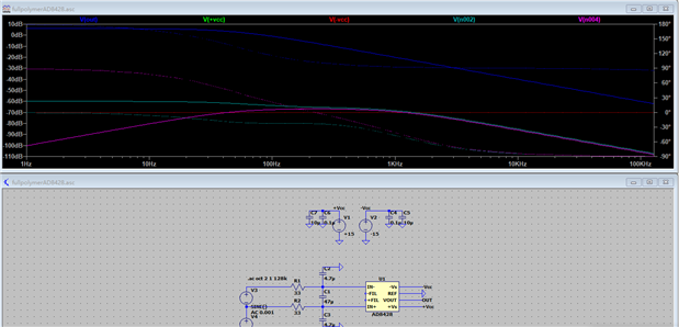
The schematic in LTspice shall be as follows ,then Run the simulation,
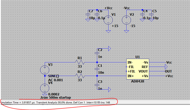
The transient simulation results shall be,

with BOM listed below.
But, such experimental schematic is serious flawed. Since most of the capacitor used in this design shall be MLCC. The polymer capacitor is much large in size, with minimum of 2.2uF. The feature of polymer capacitor can not be tested.
2.2.2 Now, the best choice is to use as many as possible the polymer capacitor in this design. The performance of Amplifier may not be best in the design, but the operation of amlifier and capacitor can be fully studied first.
Polymer capacitor with features of large capcitance, low ESR/ESL and excellent caracteristic at low temperatures as well as high reliability. The last two feature is obvious with dry type material and explosive-safe.
That is good for,
- Backup. With low ESR, low ESL and large capacitance, polymer capacitor can response to change in load in the way other capacitor can not. Super capacitor is good for backup, with capacitor of more than 10F and even larger size, not fit for PCB.
- Smoothing. Polymer smoothing capacitor for the switching power supply units can suppress ripple votage better.
- Bypass and decoupling. Polymer capacitor with low EST can supress noise fupplied from Power Supply line into ICs, which may cause the IC malfunction, this may lead to unstable Gain for amplifier.
- Filtering. There are RC filter, LC filer, ∏ type filer, and T type filter. The low-pass filter can reduce noise in mixed digital-analog circuit, filtering unwanted frequency components. Gain characteristic of RC filter shall be studied. In amplifier, cutoff frequency shall be calculated in selecting values of R-C.
Here is equivalent diagram for capacitor
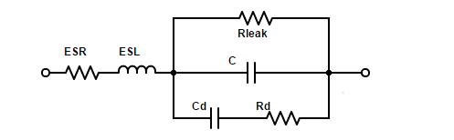
In most cases,ESL Rleak, Cd and Rd is small enough not to considered. Here is the demonstration diagram shows the Frequency vs Z or ESR.

Then update above design with more polymer capacitors used for filering and bypass.
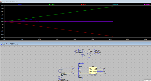
2.2.3 Updated Design with Polymer Capacitor as follows,
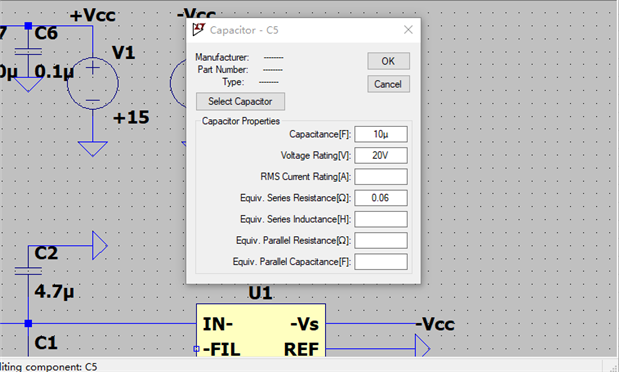
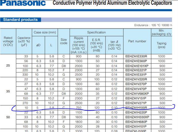
both C5 and C7 shall be 10uF ,Conductive Polymer Aluminum Solid Capacitor, 10 µF, 20 V, Radial Can - SMD, OS-CON, SVP Series
both C2 and C3 shall be 4.7uF ,Tantalum Polymer Capacitor, 4.7 µF, 10 V, POSCAP, TPU Series,
C1 shall be MLCC since AC is applied, polarized capacitor can not work right. With only 4.7uF at hand, but it shall be 10x times of C2 and C3. This can only be experimental setting in this case.
C4 and C6 shall be 0.1uF MLCC, since the the polymer capacitor can not be as small as 0.1uF. While 0.1 uF is needed for high-frequency filtering near IC pins.
Here is the simulation result.
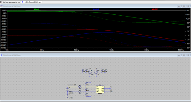
In this simulation, ESR is filled in the parameters of the capacitors.
Other simulation like transient simulation and AC sweep analysis can be done with different capacitor ratings. That is really fun and useful. Many wrong idea can be tested before burning the chips.
There is not enough time to explain them all, part of the results shown below.

After simulation, design the PCB
03. Schemtic Design and PCB Design
3.1 There have been many EDA tools. CADSTAR is what I used most. While for simple schematic like this, some online web IDE is enough. https://easyeda.com/ is good for this case. That is fairly easy to use even for beginners.
Let start in easy steps with automatic routing and designing,
Schematic design

Generated PCB automatically,
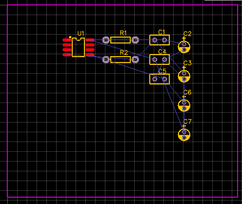
Auto-routing,

3D view of generated PCB board,

It is obvious that it is not good design. More adjustment shall be made.
3.2 Updated design with Adjusted Position, Package, then auto-routine with the following results,
Update the package according to Datasheet,
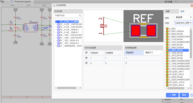

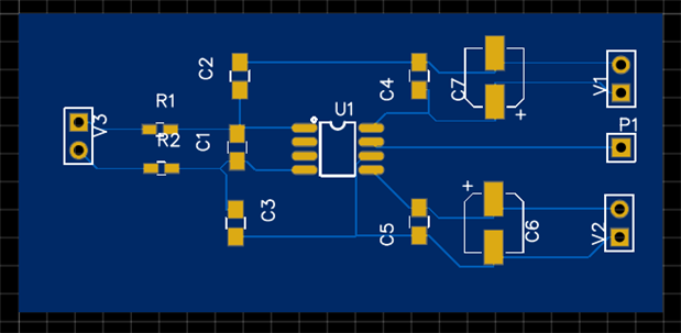
Finally, the Schematic diagram,

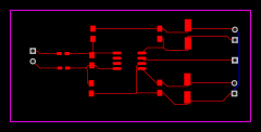
Auto-routine after manually adjustment, the Blue wire is on bottom layer

Last step, Output the BOM, and Print the PCB design for PCB making.

04. PCB making and Solding
4.1 Best choice is sending the Design Gerber files to manufacture, normally they charge little for pilot design and deliver the PCB board within one week in China.
One week is too long, why not make it one hour, do it by myself, I can make it one hour.
Luckily, I happen to have all the DIY material.

I shall use the easiest way to do and make quick PCB. What I need is only one Oil-paint maker and PCB Copper Corrosive, Sodium persulfate. in that, Na2S2O8+Cu=Na2SO4+CuSO4

Fairly simple in steps One, Two, Three.
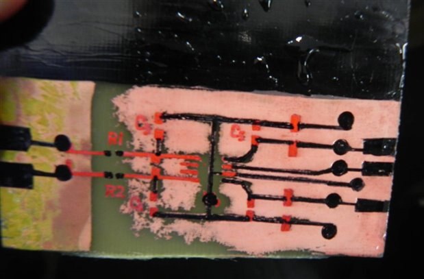
First, Draw the schematic diagram on the Copper Clad Laminate, patient and accuration is needed when there is SMD parts. Use your imagination as you can. To save time, I paint one layer black totally, that is ground layer in the design. I will use fly wire in this case.
.


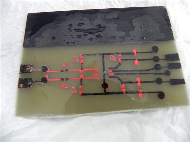
Second, dip the CCL in one bottle with Sodium persulfate solution. Normally it takes 10 minutes, thirty minutes is OK if paint well and water-proof for copper clad layer


Third and the last, clean the board and remove the paint. That is easy, use anything you can remove grease.

Well, next steps for hand solding.
4.2 Solding
There would take not much time, but the polarity of polymer capacitor shall be verified.
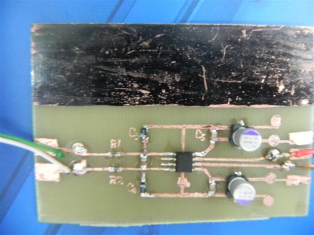
Visual check for soldering point is neccesary. Look closer, C2 in the PCB is not well positioned. But the AD8428 is right in position.

4.3 Now the design and PCB making is completed. In fact, most of the work can be outsourced. Send the design and BOM to manufacture via e-mail, they can quote price including solding common resistor and capacitors , you can add important part like amplifier when receiving the board. That would be in much higher standard, but you must make sure the circuit is good.
Manually do all the work alone take more time, but you can correct your mistake very soon. Creating one new PCB will take only one more hour. Poor in quality, but good for experiment.
05. Test with MKR1000
5.1 In my proposed experiment plan, I would use Arduino MKR 1000 to receiving signals in ADC channel and send reading back to cloud. Here is basic sketch tested with Arduino Web Editor
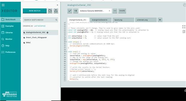
Reads an analog input pin, maps the result to a range from 0 to 255 and prints the results to the Serial Monitor. The circuit:the analog pin A0 as input ranging 0~+3.3V.
const int analogInPin = A0;  // Analog input pin that the potentiometer is attached to
const int analogOutPin = 9; // Analog output pin that the LED is attached to


int sensorValue = 0;        // value read from the pot
int outputValue = 0;        // value output to the PWM (analog out)


void setup() {
  // initialize serial communications at 9600 bps:
  Serial.begin(115200);
}


void loop() {
  sensorValue = analogRead(analogInPin);
  // map it to the range of the analog out:
  outputValue = map(sensorValue, 0, 1023, 0, 255);
  // change the analog out value:
 //Serial.print("sensor = ");
  Serial.print(sensorValue);


  // wait 2 milliseconds before the next loop for the analog-to-digital
  // converter to settle after the last reading:
  delay(2);
}
5.2 Power up the board and take on the experiment
Wiring the MKR1000 board and Demo Board , A0 and GND in MKR1000 vs OUTPUT and GND. IN01 and IN02 shall connect round metal pad attached to chest. Powered with 2x9V battery.


Then plug the Desktop USB ti MKR, and one Serial Port software Serial Hunter,rating 115200-N-8-1.

Now the data flush into the screen in 1kHz sample rate. Since the ECG signal frequency ranging 0.1Hz- 200Hz, such sample freqency is OK for demo purpose.
All data can be saved in .txt format for further research.
The visualization function is not OK now.
06. Conclusion
6.1 In this experiment report, I try to outline the full picture of how to study one electronic components. From basic parameter measuring, to circuit design, PCB design and final build. And finally, how such demo circuit can lead to one potential REAL APPLICATION prototype build with Arduino Board.
There have been many flaws and problems, even since my original plan. With thoroughly research and experiment, it occurs to me that some of the idea is totally wrong. It is grateful for Michael Kellett who give many useful instructions and suggestions.
This experiment includes both polymer capacitor and one Advanced Instrument Amplifier, digging and research become one exciting journey of exploration, even the tight schedule and ticking submission deadline are strong engines pushing me hard.
Obviously, this final report is far from good. I even doubt if it can reach pass grade.
While , I am happy to have such a chance to post this blog for review of you all.
6.2 The features of compact size and large rating.
That is fairly obviously. The following photo tells more than I can describe.


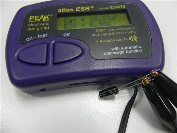
6.3 Small ESR
That is evident too, here is the AL electrolytic capacitor with ESR of 0.9ohm, but for same size the polymer capacitor is 0.30ohm.
As with supercapacitor with much larger size, the ESR is as high as 3.60ohm in 1.0F.
6.4 Measurement Bias and errors
The reading from fluke 106 normally less than ESR70,
Conductive Polymer Tantalum Solid Capacitor, 220 µF and Tantalum Polymer Capacitor, 47 µF, the bias is too much. That is one problems pending for further research.
The measuring of capacitor is not easy, for ESR , more difficult. This ESR reading is not DC resistance, it works only on low freqency AC, around 100kHz AC. Therefore, the ESR reading shall be adjusted if used in High frequency range.

6.5 Application of polymer capacitor in Decoupling
Decoupling is important in ampilifer, high frequency noise can enter into the amplifier and feedback to input circuit to distort the amplifier. The decoupling capacitor is important and shall be put near to the IC.
The decoupling capacitor of 0.1μF normally comes with 5nH of distributed inductance. The resonance frequency is about 7MHz, as in,
![]()
It is good to get rid of noise below 7~10MHz. That is why 0.1μF capacitor is recommended in most vendor suggestion. This capacitor is so small that polymer capacitor can not reach.
Polymer capacitor shall be used in parallel to supress lower frequency noise. Then 10μF capacitor can be polymer capacitor. With ESR much lower, in this experiment , that is 0.3ohm vs 0.9 ohm. That would be better.
6.6 Application of polymer capacitor in Bypass

Bypass capacitor can creat one return passage for high frequency noise and block the leackage of low frequency input signal. That is what good for medical application of where useful ECG signal is below 200Hz.
The selection of bypass capacitor shall refer to Xc = 1/(ωC)= 1/(2πfC). The larger the Capacity, the lower the capacitive reactance is.
6.7 Special feature on Instrument Amplifier AD8428
AD8428 is in three amplifier configuration.
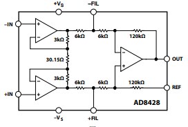
The CD and Cc work in different ways. CD works as different mode filter, and Cc works as common mode filter. The resonance frequency shall be calculated as formulor below,

But larger capacity can reduce the value of Bandwidth x Gain. The band-width of amplifier will be reduced.
Therefore, the application scope and features of input signal shall be researched before design and selecting electronic components.
6.8 FurtherTest with Polymer Capacitor
- It is good to compare with simlilar circuit with normal capacitor like MLCC to see what is the result. That part have to be done as another experiment and can not be included in this report.
- The power supply circuit for the amplifier is important, and polymer capacitor would be good in DC-DC buck-boost power design.
| PCB_PCB-polymercap_20190605115537.pdf | |
| Schematic_PolymerCapacitorAD8428_Sheet-Schematic_20190605115114.pdf | |
 | |


Top Comments