element14 Community
element14 Community
    Register Log In
  • Site
  • Search
  • Log In Register
  • About Us
  • Community Hub
    Community Hub
    • What's New on element14
    • Feedback and Support
    • Benefits of Membership
    • Personal Blogs
    • Members Area
    • Achievement Levels
  • Learn
    Learn
    • Ask an Expert
    • eBooks
    • element14 presents
    • Learning Center
    • Tech Spotlight
    • STEM Academy
    • Webinars, Training and Events
    • Learning Groups
  • Technologies
    Technologies
    • 3D Printing
    • FPGA
    • Industrial Automation
    • Internet of Things
    • Power & Energy
    • Sensors
    • Technology Groups
  • Challenges & Projects
    Challenges & Projects
    • Design Challenges
    • element14 presents Projects
    • Project14
    • Arduino Projects
    • Raspberry Pi Projects
    • Project Groups
  • Products
    Products
    • Arduino
    • Avnet Boards Community
    • Dev Tools
    • Manufacturers
    • Multicomp Pro
    • Product Groups
    • Raspberry Pi
    • RoadTests & Reviews
  • Store
    Store
    • Visit Your Store
    • Choose another store...
      • Europe
      •  Austria (German)
      •  Belgium (Dutch, French)
      •  Bulgaria (Bulgarian)
      •  Czech Republic (Czech)
      •  Denmark (Danish)
      •  Estonia (Estonian)
      •  Finland (Finnish)
      •  France (French)
      •  Germany (German)
      •  Hungary (Hungarian)
      •  Ireland
      •  Israel
      •  Italy (Italian)
      •  Latvia (Latvian)
      •  
      •  Lithuania (Lithuanian)
      •  Netherlands (Dutch)
      •  Norway (Norwegian)
      •  Poland (Polish)
      •  Portugal (Portuguese)
      •  Romania (Romanian)
      •  Russia (Russian)
      •  Slovakia (Slovak)
      •  Slovenia (Slovenian)
      •  Spain (Spanish)
      •  Sweden (Swedish)
      •  Switzerland(German, French)
      •  Turkey (Turkish)
      •  United Kingdom
      • Asia Pacific
      •  Australia
      •  China
      •  Hong Kong
      •  India
      •  Korea (Korean)
      •  Malaysia
      •  New Zealand
      •  Philippines
      •  Singapore
      •  Taiwan
      •  Thailand (Thai)
      • Americas
      •  Brazil (Portuguese)
      •  Canada
      •  Mexico (Spanish)
      •  United States
      Can't find the country/region you're looking for? Visit our export site or find a local distributor.
  • Translate
  • Profile
  • Settings
Experimenting with Polymer Capacitors
  • Challenges & Projects
  • Design Challenges
  • Experimenting with Polymer Capacitors
  • More
  • Cancel
Experimenting with Polymer Capacitors
Blog Capacitor Leakage Current over Temperature
  • Blog
  • Forum
  • Documents
  • Polls
  • Files
  • Mentions
  • Sub-Groups
  • Tags
  • More
  • Cancel
  • New
  • Share
  • More
  • Cancel
Group Actions
  • Group RSS
  • More
  • Cancel
Engagement
  • Author Author: michaelkellett
  • Date Created: 26 Jun 2019 2:52 PM Date Created
  • Views 3170 views
  • Likes 9 likes
  • Comments 5 comments
  • polymer capacitor
Related
Recommended

Capacitor Leakage Current over Temperature

michaelkellett
michaelkellett
26 Jun 2019

I was prompted to do this series of experiments by neuromodulator interesting blog posts. The puzzling thing abut his results is the apparent linking of rate of change of temperature with leakage current.


I set up my own test arrangement using and Espec SH262 Benchtop Temperature and Humidity chamber to control the temperature of the capacitors and a Keysight 34972A34972A Data Acquisition system to do the leakage current measurements.


A TTi PL-155-P power supply was used to supply the bias voltage.


Each capacitor was connected in series with a 1000R metal film resistor and the 34972A34972A, on the 10mV range, was used to measure the voltage across the resistor from which the current can be determined. A set of 8 measurements was taken every 20 seconds. The whole setup was controlled by a PC via Ethernet.


I wanted to change the temperature as quickly as possible to investigate the effect of rate of change of temperature so I set the ramp rate of the SH262 to 3  degrees/minute, which it can just manage when heating and not quite manage when cooling. The temperature was changed from -20C to +80C with 2 hours dwell at each extreme. I ran the experiment for 10 complete cycles (50 hours).


The power supply has turned out to be a bit too noisy (it's the dominant source of noise) so I will add a filter to it for the next test run.


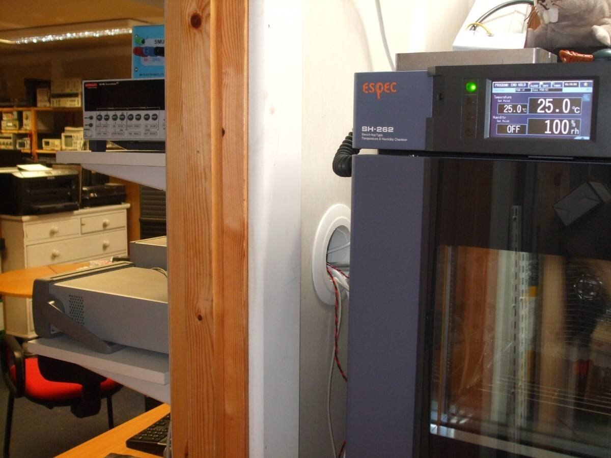
I wanted to try a range of different types of parts so I used 2 samples each of 4 types:


image

The only 10uF Electrolytics I to hand are more than 17 years old an I bought them second hand (unused) at an auction - I'll try them in the next test.

The Rubycon 47uF are at least quite new, although not the ideal value.


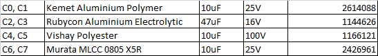
The test board looks like this:


image


And in the test chamber:


image


I wrote a programme in VB6 to control the instruments and talk to the test chamber. The computer  and the instruments live inside my nice insulated room but the chamber lives outside because it's a little noisy but also generates a lot of heat when cooling rapidly.


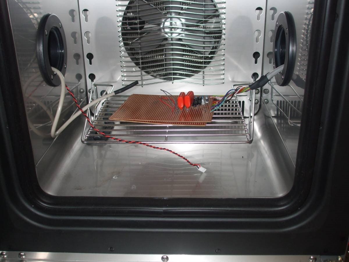
This is my setup for testing things over temperature:

image


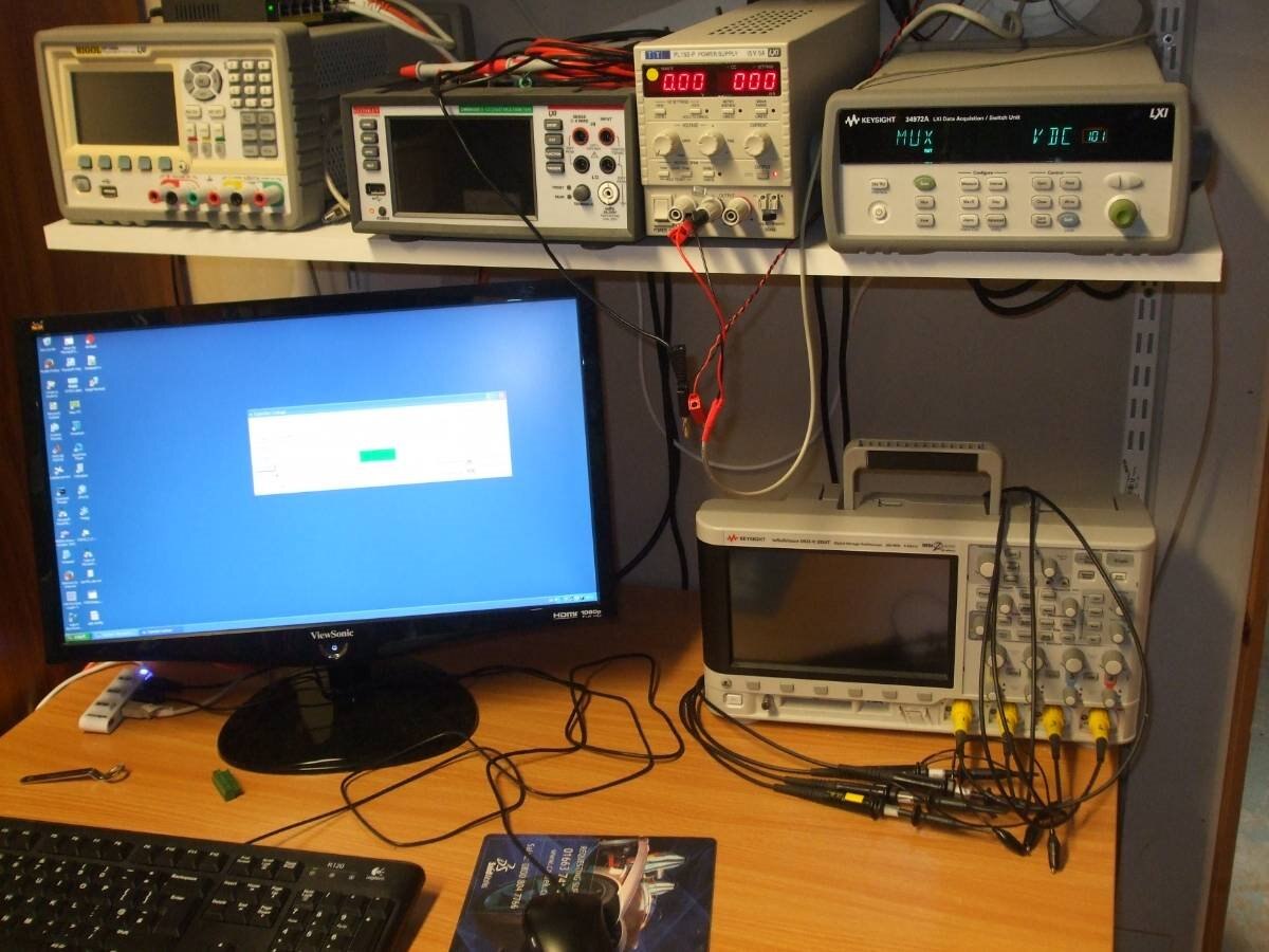
And this is how I keep the noise and heat from the temperature cycler at bay:


image


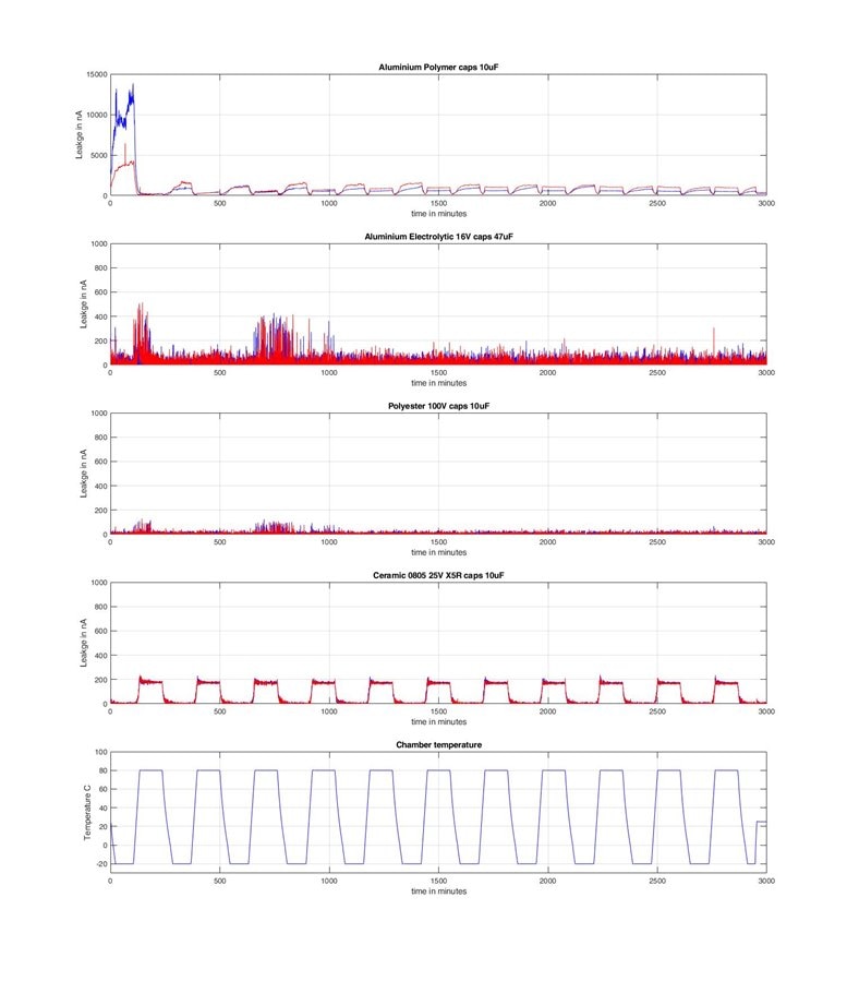
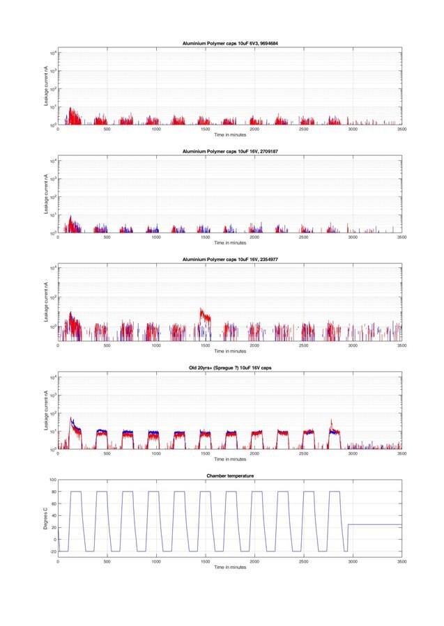
Test results, linear plot:


image

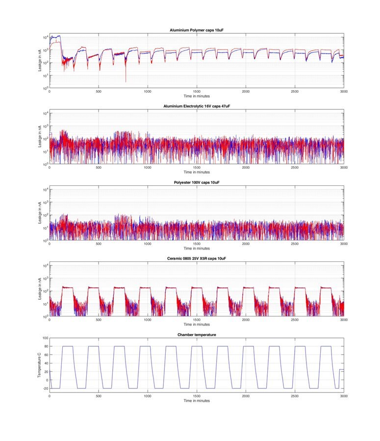
Test results, log plot

image

There a few interesting things in the results.


First some general points:

The system noise was too high (more on this later) and there was some kind of a noise burst during the first high temperature dwell time. Since it affected all for capacitor types and wasn't repeated we'll ignore it.

This was one test of a very small number of parts - beware of this and don't get carried away with drawing conclusions.

As far as I can tell none of the parts was out of spec, so while I may talk about high leakage current please don't forget that highest value I measured was 10uA !!!!


The Aluminium Polymer caps had the highest leakage current, with much higher leakage current over the first cycle. There is evidence of the effect picked up by neuromodulator and once the capacitors had settled in the dt/dT effect was greater than the effect of temperature. My AlPoly caps had lower leakage when hot than when cold.


The unexpected star of this test was the Aluminium Electrolytics from Rubycon - leakage current average less than 10nA (over temperature) and cheap - about 10p each. I measured the ESR at about 0.3R.


The Vishay Polyester capacitors are huge, rated for 100V, quite pricey and very low leakage. They are mainly included here as a reference point. The ESR is very low as well. They would be great in filters but not normally much use in power supplies (self resonant frequency is 390kHz for this part, lower capacitance values are much better).


The Murata MLCCs are a bit of  a mixed bag, my capacitor tester had trouble measuring them - giving silly (high) values of ESR at low frequencies and low capacitance values at higher frequencies. The leakage current is very temperature dependent but well within spec.


Noise


Once the test was complete I let the system settle and stabilise for several hours at 25C and took some more measurements as I set the bias supply to 0V and then shorted it out:

image


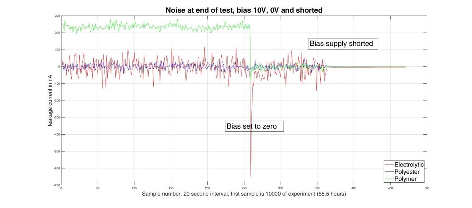
When the bias is reduced to 0V the leakage current disappears as would be expected but the noise continues until the bias supply is shorted out. It looks as if noise from the power supply is bad enough to cause a problem here so I shall experiment with filtering it.


Next Test


For my next test run I shall get some caps like those tested by neuromodulator and try them, along with the ancient 10uF parts.


Conclusions (very preliminary)

All these capacitor types performed vastly better than spec (well actually the Vishay ones might not have done but they are so good I can't tell image).

This is not ideal- it's a problem; because it means that experimental results on one or two samples of a design will tell you nothing at all about how well it might do in mass production. So if leakage current matters to you then you must work with worst case specified values. For my Kemet 10uF caps that would be 120uA at 25C rather than the measured 1uA.

There does seem to be a dt/dT effect on the leakage current of the Aluminium Polymer caps but the magnitude is very low.


When choosing capacitors there is no best ! The Aluminium Polymer parts have very low ESR, maybe slightly worse leakage than MLCC but there isn't much in it, so pretty good for switching power supplies. MLCC are also good for power supplies but be very careful about very high K dielectrics.

For low cost good performance the classic Aluminium Electrolytic takes some beating, and remember that very low ESR caps used in designs that expected Aluminium Electrolytic caps can make them unstable.


More Testing 4th JULY 2019

Since I was unable to duplicate neuromodulator's results with the capacitors I had to hand I bought three different types of surface mount Aluminium Ploymer capacitor for some more tests.


image

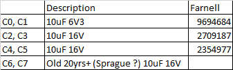
C0, C1 are the same type that NM tested.

C6 and C7 are included in the hope of seeing something really bad, and checking out the commonly held belief that electrolytic have a poor shelf life.


I added a filter to the power supply (56R in series and then 33000uF to ground, this reduced the noise considerably - down to about 1nA RMS


For the first test run I used 5V bias to respect the ratings of C0 and C1

In each of the first four sub graphs the blue trace is C0,C2, C4 or C6 and the red trace C1, C3, C5 or C7


image

Very little seems to be happening with 5V bias so I increased it to 10V. (NB C0 and C1 are only rated for 6.3V).


image


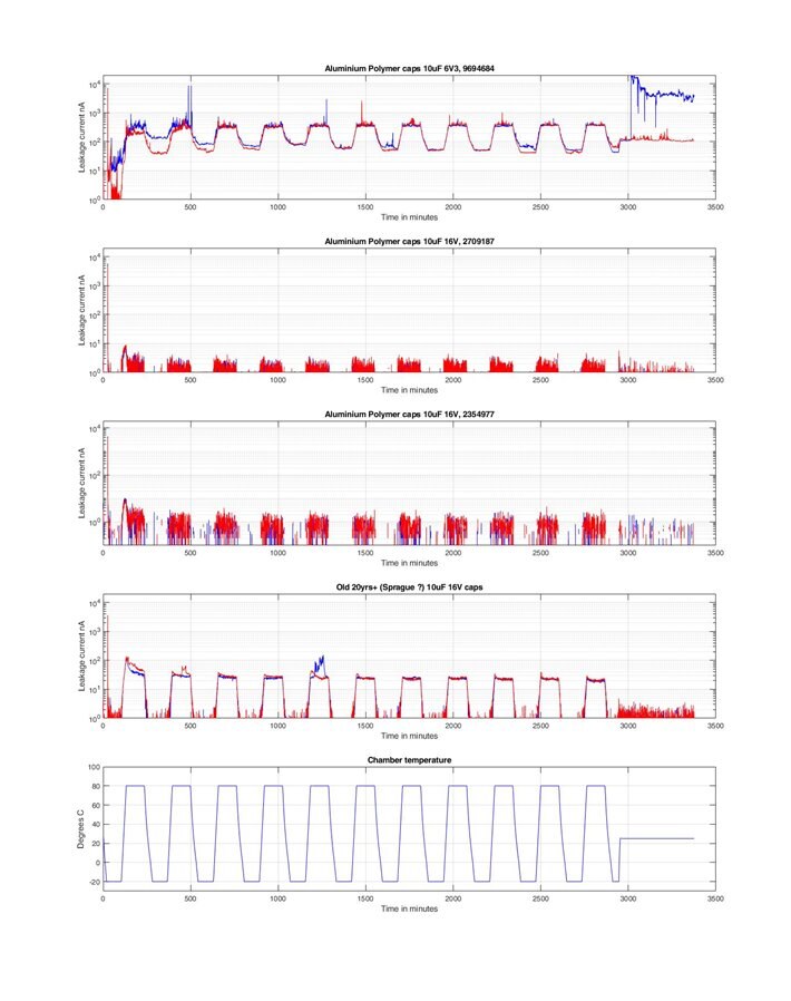
Now things are a bit more interesting, C0 and C1 leakage has incensed significantly and after several temperature cycles C0 could be said to have

failed (except that the leakage current only peaked to about 3.5uA which isn't actually out of spec and I was over volting it !)


The old electrolytic comes out of this pretty well, leakage current rising to about 30nA at 80C with 10V bias.


There is a little evidence of a rate of change of temperature effect but it seems to mainly affect only the first temperature cycle of each test.

C0 and C1 show almost no rate effect and very low leakage current under fair operating conditions.

C2 - C5 only show a very small rate of change effect in the first cycle but the maximum leakage current is very low (max 10nA with 10V bias)

C7 shows the rate effect to a small extent right way through the test.


I was not able to reproduce NM's results for C0 and C1 but this could be for a variety of reasons:

my system noise, even with the filter, was a bit higher and this would tend to mask the effect.

my rate of change of temperature was a little slower (3C/min rather than just over 4)

we may not have handled the capacitors in exactly the same way (we both had to solder wires to them).


Conclusion

All the capacitors measured had leakage currents orders of magnitude less than specified (or below the capability of my test setup to measure).

The rate of temperature change does seem to affect the leakage current but at very low levels.

If equipment is designed to operate correctly at specified maximum leakage currents the effect of rate of change of temperature is very unlikely to be an issue.

None of the capacitors tested showed any tendency for degradation of the leakage current performance over the 10 cycle test (under permitted voltage bias).

Applying 10V bias to a 6.3V capacitor caused it obvious signs of stress but it was still within spec for leakage current at the end of the test.


MK

  • Sign in to reply

Top Comments

  • neuromodulator
    neuromodulator over 6 years ago +5
    Very nice report Michael, the chamber and the parallel recording through a DAQ surely help a lot in making the testing much more rigorous! I'm currently working on designing a chamber to do what you just…
  • michaelkellett
    michaelkellett over 6 years ago in reply to neuromodulator +5
    There were two caps of each type, one is blue (caps 0,2,4,6) and the others (1,3,5,7) are red. Sorry for not saying ! I'll try a different rate - but I can only go slower ! I had my instrument on 100PLC…
  • genebren
    genebren over 6 years ago +4
    Very interesting tests and data. I look forward to your further tests and conclusions. Gene
  • neuromodulator
    neuromodulator over 6 years ago in reply to michaelkellett

    Checking again your plots, the aluminum poly shows an interesting property, at -20 the leakage is higher than at 80. It might be interesting to perform a very slow ramp up and down to see where it reaches its minimum. I suspect that if the ramp is slow enough the leakage currents will be identical, independent of the direction of the ramp, unless capacitors "long memory".


    If you try different dT/dt try something like 2 C/min, 1 C/min, 500 mC/min, and so on, it may better highlight the effect of the dT/dt over the leakage.

    • Cancel
    • Vote Up +3 Vote Down
    • Sign in to reply
    • More
    • Cancel
  • michaelkellett
    michaelkellett over 6 years ago in reply to neuromodulator

    There were two caps of each type, one is blue (caps 0,2,4,6) and the others (1,3,5,7) are red. Sorry for not saying !

    I'll try a different rate - but I can only go slower !

    I had my instrument on 100PLC and single reading - probably no a lot different.

    With the noise filter (56R, 33000uF) on the power supply I'm down to 1nA RMS noise.


    I may get my next test (with some caps exactly like yours)  started today before I'm away for three days  - depends on Farnell and UPS.


    MK

    • Cancel
    • Vote Up +5 Vote Down
    • Sign in to reply
    • More
    • Cancel
  • shabaz
    shabaz over 6 years ago

    Hi Michael,


    Very interesting results!

    Recently I took a look at a couple of computer motherboards, to see if I could spot any trends. One was an old motherboard (2010), and the other was about 5 years more recent in manufacture. They were from different manufacturers, both major brands, and both intended for server use, not consumer.

    The older motherboard had (as expected) lots of MLCC, and the remainder were a mix of aluminium polymer, some tantalum (clustered in one part of the design only, near some connector), and some aluminium electrolytic. There were also some I could not determine (rectangular case like tantalum, but all black in colour, they may have been tantalum polymer - I could not tell from the code on top).

    The newer motherboard had the MLCC as expected, and then _all_others were alu polymer, save one, which was aluminium electrolytic. There were zero tantalum. The lone alu electrolytic (Nichicon HM series) was at a corner of the board, perhaps it was decided it would run cool and have a long life there. It was part of the output of a DC-DC converter, in parallel with some MLCC. The DC-DC converter chip was the same as that used in a few other places of the board, but the other places used alu polymer in parallel with some MLCC. (EDIT: it was 1000uF 16V, so perhaps that DC-DC converter has a higher voltage output, for some ancillary purpose not as power-intensive as the lower-voltage output DC-DC converters on the rest of the motherboard).

    It was interesting seeing the complete absence of tantalum, at least for that server motherboard, and near-absence 10 years ago. For a different market (with ultra high reliability requirement) out of uni, the capacitors were almost entirely tantalum (+ MLCC), no alu electrolytics.. but then there there were no alu polymer available at the time.

    • Cancel
    • Vote Up +4 Vote Down
    • Sign in to reply
    • More
    • Cancel
  • neuromodulator
    neuromodulator over 6 years ago

    Very nice report Michael, the chamber and the parallel recording through a DAQ surely help a lot in making the testing much more rigorous!

    I'm currently working on designing a chamber to do what you just did, test different arbitrary temperature curves...


    To reduce noise I set the number of power line cycles to 2, and averaged 100 measurements, this took approximately 3 s.


    In the plots, which is current, the red or the blue? What is the other color?

    As there appears to be hysteresis, it would be interesting to see an i vs T plot.

    To see the effect of the dT/dt it would also be interesting to test different values of dT/dt.

    • Cancel
    • Vote Up +5 Vote Down
    • Sign in to reply
    • More
    • Cancel
  • genebren
    genebren over 6 years ago

    Very interesting tests and data.  I look forward to your further tests and conclusions.


    Gene

    • Cancel
    • Vote Up +4 Vote Down
    • Sign in to reply
    • More
    • Cancel
element14 Community

element14 is the first online community specifically for engineers. Connect with your peers and get expert answers to your questions.

  • Members
  • Learn
  • Technologies
  • Challenges & Projects
  • Products
  • Store
  • About Us
  • Feedback & Support
  • FAQs
  • Terms of Use
  • Privacy Policy
  • Legal and Copyright Notices
  • Sitemap
  • Cookies

An Avnet Company © 2025 Premier Farnell Limited. All Rights Reserved.

Premier Farnell Ltd, registered in England and Wales (no 00876412), registered office: Farnell House, Forge Lane, Leeds LS12 2NE.

ICP 备案号 10220084.

Follow element14

  • X
  • Facebook
  • linkedin
  • YouTube