


I've used a number of different buck converters to experiment with small solar panels. Since this is a relatively short challenge I decided to modify an existing converter circuit rather than trying to design and build a new one. Here is the buck converter circuit that I'm going to use:

It is a relatively inexpensive Chinese converter that I got from Amazon.


I am going to evaluate the performance of the existing circuit and then replace the 220mF aluminum electrolytic output filter capacitor with an equivalent polymer capacitor and compare the results. For this test I'm going to use a DC input source so that I am only looking at the noise from the converter itself. This is an adjustable converter but I'm just going to test it with a 10V input and 5V output.
Here is my test setup:

I have a function generator driving a MOSFET switched resistive load for the switching tests,
Surprises!!
I'm going to admit that although I've used a few variations of buck and buck/boost converters that I have always checked them with a DMM rather than a scope. I guess I'm learning a valuable lesson. I've recently been unpleasantly surprised with the awful performance of micro USB power supplies for the Raspberry Pi. My surprise with the buck converter was the amount of ripple that was present at the output when it was loaded. The LM2596 has a 150KHz internal oscillator so it should allow for relatively small output filter components.
No load output noise:

This didn't look too bad, around 20mV at 20ms or 50KHz.
500mA load noise:

Now there is 200mV of ripple at still at about 50KHz. This is with a static resistive load. The DMM only showed a DC drop of 50mV (4.95V). The noise increased to about 250mV at a 1A load and had the same waveshape.
Then I tried switching the 500mA load at about 1Hz.
It appears that the ripple stayed at about 200mV but the DC drop is now about 250mV. Most 5V circuits would probably still work but there wouldn't be much margin for IR drop or other effects in the wiring. I was measuring at the output of the supply rather than at the load (about 4 inches away). Funny story - I've learned that test probes are not thermally robust (I guess I don't pay enough for decent ones). I've learned never to clip probes close to anything dissipating more than a few Watts. I melted the plastic casing of a scope probe that way.
Here's a zoomed in view (the yellow waveform is the gate signal to the MOSFET that is switching the load).

I changed to AC coupled to get better voltage resolution (apologies but the Ch2 vertical scale is really 50mV/div - had the probe multiplier wrong in this picture).
Replace the output capacitor
I removed the 220mF aluminum electrolytic and measured it on the ESR70.
C = 205.8mF
ESR = 0.20W
I measured the 220F polymer electrolytic that I was replacing it with:
C = 220.1mF
ESR = 0.04W
The other difference is that the standard cap is rated to 35V and the Polymer is rated to 20V.
Surprise 2
The no load noise looked great but I was in for a surprise when I checked the loaded result!
No load output noise:

No load ripple is 5X better!
500mA load noise:

Ripple is more than 100mV greater than the standard cap! On closer examination the characteristic of the ripple is different - the frequency is much lower, around 7KHz vs 50KHz and the DC level is at 5V.
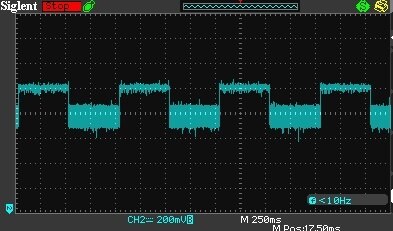
500mA load switched at about 1Hz.

You can see there is no DC offset when the load switches.
Zoomed in view of 500mA load switched at about 1Hz. (Ch2 vertical scale is 50mV/div)

In this view it was apparent that the waveshape was irregular and the amplitude was wandering around. This looks more like I created an instability in the feedback control loop.
At this point I decided that I should read the LM2596 spec and I came across the following nugget in the Application Information:

So, it appears that I created an instability with too low an ESR value! I think at this point I think I've exhausted all the energy that I had allocated to this challenge. I think in the future I'd like to simulate this design and try to fix it. I think that I just need to find the correct value for a compensation cap in the feedback loop.
In summary:
This challenge has been lots of fun and I've (re)learned a lot. Thanks to Element14 for selecting me as a sponsored challenger. The ESR70 is a great tool. I'm sure I'll put it to good use. Polymer caps look great. It appears that they do a great job with output ripple but you can't assume that there won't be any side effects.
And the lesson that I always relearn - don't bet your life on power supplies meeting their specified performance.
Top Comments