element14 Community
element14 Community
    Register Log In
  • Site
  • Search
  • Log In Register
  • About Us
  • Community Hub
    Community Hub
    • What's New on element14
    • Feedback and Support
    • Benefits of Membership
    • Personal Blogs
    • Members Area
    • Achievement Levels
  • Learn
    Learn
    • Ask an Expert
    • eBooks
    • element14 presents
    • Learning Center
    • Tech Spotlight
    • STEM Academy
    • Webinars, Training and Events
    • Learning Groups
  • Technologies
    Technologies
    • 3D Printing
    • FPGA
    • Industrial Automation
    • Internet of Things
    • Power & Energy
    • Sensors
    • Technology Groups
  • Challenges & Projects
    Challenges & Projects
    • Design Challenges
    • element14 presents Projects
    • Project14
    • Arduino Projects
    • Raspberry Pi Projects
    • Project Groups
  • Products
    Products
    • Arduino
    • Avnet Boards Community
    • Dev Tools
    • Manufacturers
    • Multicomp Pro
    • Product Groups
    • Raspberry Pi
    • RoadTests & Reviews
  • Store
    Store
    • Visit Your Store
    • Choose another store...
      • Europe
      •  Austria (German)
      •  Belgium (Dutch, French)
      •  Bulgaria (Bulgarian)
      •  Czech Republic (Czech)
      •  Denmark (Danish)
      •  Estonia (Estonian)
      •  Finland (Finnish)
      •  France (French)
      •  Germany (German)
      •  Hungary (Hungarian)
      •  Ireland
      •  Israel
      •  Italy (Italian)
      •  Latvia (Latvian)
      •  
      •  Lithuania (Lithuanian)
      •  Netherlands (Dutch)
      •  Norway (Norwegian)
      •  Poland (Polish)
      •  Portugal (Portuguese)
      •  Romania (Romanian)
      •  Russia (Russian)
      •  Slovakia (Slovak)
      •  Slovenia (Slovenian)
      •  Spain (Spanish)
      •  Sweden (Swedish)
      •  Switzerland(German, French)
      •  Turkey (Turkish)
      •  United Kingdom
      • Asia Pacific
      •  Australia
      •  China
      •  Hong Kong
      •  India
      •  Korea (Korean)
      •  Malaysia
      •  New Zealand
      •  Philippines
      •  Singapore
      •  Taiwan
      •  Thailand (Thai)
      • Americas
      •  Brazil (Portuguese)
      •  Canada
      •  Mexico (Spanish)
      •  United States
      Can't find the country/region you're looking for? Visit our export site or find a local distributor.
  • Translate
  • Profile
  • Settings
Experimenting with Polymer Capacitors
  • Challenges & Projects
  • Design Challenges
  • Experimenting with Polymer Capacitors
  • More
  • Cancel
Experimenting with Polymer Capacitors
Blog Using Polymer Capacitors for Supply De-coupling in the Current Amplifier
  • Blog
  • Forum
  • Documents
  • Polls
  • Files
  • Mentions
  • Sub-Groups
  • Tags
  • More
  • Cancel
  • New
  • Share
  • More
  • Cancel
Group Actions
  • Group RSS
  • More
  • Cancel
Engagement
  • Author Author: three-phase
  • Date Created: 30 May 2019 9:22 PM Date Created
  • Views 1124 views
  • Likes 9 likes
  • Comments 4 comments
  • experimenting with polymer capacitors
Related
Recommended

Using Polymer Capacitors for Supply De-coupling in the Current Amplifier

three-phase
three-phase
30 May 2019

This is my unofficial entry into the Experimenting with Polymer Capacitors challenge - I never applied for the capacitor kit, as my little escapades into electronics are very ad hoc and I felt that a kit of capacitors would go to waste on me, and it would be better off going to people who would make better use of it than I. The current amplifier circuit I am going to use for the tests was designed with radial through-hole capacitors, of which there were not any within the kit offered, makes a further reason for not applying.


I am basing my work around the current amplifier circuit that I entered into the Electromagnetism Project14 competition, alongside the current clamp tables that I was winding. Some original comments around the supply de-coupling capacitors on the amplifier were that they may need to be increased. I have very little knowledge on the subject, and therefore I just stuck with the design concept detailed in the data sheet for the OPA548 from Texas Instruments.


image

Up until now, I have just assumed that this de-coupling is perfectly adequate for the circuit, and I have concentrated on obtaining the appropriate output currents to match the coils.


My research into de-coupling capacitors has been around a tutorial provided by Analogue Devices:- MT101 De-coupling Techniques. This discusses the use of larger electrolytic capacitors between 10uF and 50uF in parallel with smaller MLCC capacitors, to provide the optimal de-coupling solution. The use of Polymer capacitors due to their low ESR is also mentioned.


The original current amplifier circuit utilised a 10uF electrolytic on each supply rail in parallel with a 0.1uF ceramic. This original 10uF capacitor was physically quite small, and in itself, presents a challenge in selecting a replacement capacitor, especially with an increased size. The supply rail to the amplifier is from a 9V dual secondary transformer, giving around 14V output at no load, after the bridge rectifier and smoothing capacitors. Voltage rating of the capacitors, therefore should not be a problem.


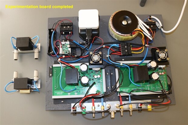
As I had spare printed circuit boards for the circuit, I decided to set two of them up for the experiments, one with electrolytic capacitors installed and the other with polymer capacitors. Both of these are fed from a single 100VA transformer, instead of having their own supply transformer. I also intended this circuit to be capable of a higher current output than the original 1A, and in the longterm I would utilise the set up to experiment with parallel and serial configurations of the amplifier output.


The circuit diagram below shows the circuit modifications made.


image


The test set up is an open board design to allow me to remove the PCBs for modifications relatively easily. Due to this, and due to the increased current output, heatsinks were added to the bridge rectifiers and a larger heatsink and fan were added to each of the amplifiers.


{gallery} Amplifier board configuration

image

Amplifier PCBs mounted on board

image

Rectifier heatsinks

image

Amplifier heatsink and fan

image

Output jack configuration

image

1 ohm load resistor and heatsink


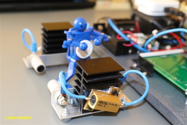
The initial test set up is to only use a 1 ohm load resistor across the output of the amplifier. The intention is to get up to the 3A maximum continuous output rating of the amplifier and potentially the 5A absolute maximum if possible. The current amplifier for my application is only required to operate between 50Hz and 20kHz, so these are the frequencies I will be concentrating on.


I have specifically looked at the Panasonic SEP and SEQP series of capacitors for the replacements. A 10uF capacitor is only available within the SEP series and I have struggled to actually obtain one within the UK, ending up with going for a special order. The SEP series are also a bit larger than the Rubycon 10uF capacitor installed, so I therefore looked at other manufacturers offerings. A Kemet Polymer capacitor from their A758 series was easily available and was of a more suitable size for replacement.


A 47uF polymer capacitor was more readily available from Panasonic from their SEQP series, as expected it is a little larger than the 10uF, but should still fit within the board. There is also a 47uF Polymer capacitor available from Kemet, that is again more favourable in size to the Panasonic. A 47uF electrolytic capacitor from Rubycon is also available to provide a performance comparison against.


image


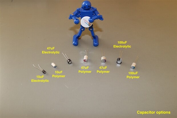
The table below summarises the capacitors I have and intend to utilise in the tests. Their basic characteristics show that they are reasonably well matched in terms of capacitance value tolerance and operating temperature. The majority of the capacitors are 25V rated, but as the capacitance increases, the polymer capacitors drop to 20V and then 16V at 100uF. A 20V version is available at 100uF from Panasonic, but its physical size is a little too much for my test board.


The can size and lead spacing does vary between the different types and the different manufacturers. In general Panasonic seemed to produce a physically larger capacitor than the others, which can lead to issues installing them on existing designs. The maximum ripple voltage varied, according to the can size and type. The lowest ripple voltage ratings were for the electrolytic capacitors, with the larger polymer capacitors from Panasonic having the highest ripple capability.


Cost is also another factor when selecting components. The prices given in the chart are UK based, excluding VAT and for minimum order quantities of 10 or less. Larger quantities would have a considerable discount in comparison. As a general guide, the polymer capacitors were more expensive than electrolytic equivalents. However, it can be seen than the endurance at rated voltage and temperature was usually higher for the polymer capacitors, with the exception being the 47uF capacitor from Nichicon.


image


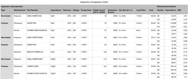
I have identified specific capacitors for installation into the C6 and C8 positions and carried out physical measurements of their properties. Naturally I do not have the ESR70 capacitance meter. I do have access to an Applent A2718A bench LCR meter and a Voltcraft LCR-300 handheld LCR meter. Strangely, the more expensive bench unit from Applent, does not have the ability to carry out an ESR measurement, but the LCR-300 does and so the checks were carried out using this instrument.


image


For the test measurements on the amplifier boards, I will supply the input signal using a sine wave generator and monitor the waveforms using a Picoscope 3404A. A separate measurement will then need to be made with the Picoscope of the ripple on the positive and negative DC supply lines. The output current from the amplifier under tests to the load, will be verified with a bench multimeter.


image


This concludes the first blog. In the second blog, I will show the results of the tests carried out.

  • Sign in to reply

Top Comments

  • jw0752
    jw0752 over 6 years ago +3
    Hi Donald, It is great that you are using this experiment to expand your knowledge and experience with the previous project. I am interested in reading your results. Your test board is very impressively…
  • shabaz
    shabaz over 6 years ago +1
    Hi Donald, Excellent blog post and project, and as jw0752 says that's a really nice set-up! By co-incidence, for a project I'm working on, I've been looking at Panasonic SEQP too, it's fantastic being…
  • three-phase
    three-phase over 6 years ago in reply to shabaz +1
    Many thanks Shabaz. It hadn't occurred to me to compare the polymer with tantalum. The 100uF I obtained were rated at 16V and the supply lines are 14V unloaded, but this drops as load is applied. I haven…
  • three-phase
    three-phase over 6 years ago in reply to jw0752

    Many thanks John,


    I have laid the board out in a logical manner for me, but it could do with a bit more space around some of the connectors. I was going to add a switch for the fans in the top left corner, but decided I would just let them run all the time for the short use that the board gets.


    Kind regards.

    • Cancel
    • Vote Up +1 Vote Down
    • Sign in to reply
    • More
    • Cancel
  • three-phase
    three-phase over 6 years ago in reply to shabaz

    Many thanks Shabaz. It hadn't occurred to me to compare the polymer with tantalum. The 100uF I obtained were rated at 16V and the supply lines are 14V unloaded, but this drops as load is applied. I haven't noted any issues, but am still organising the data I have collated.


    Kind regards.

    • Cancel
    • Vote Up +1 Vote Down
    • Sign in to reply
    • More
    • Cancel
  • shabaz
    shabaz over 6 years ago

    Hi Donald,


    Excellent blog post and project, and as jw0752 says that's a really nice set-up!

    By co-incidence, for a project I'm working on, I've been looking at Panasonic SEQP too, it's fantastic being able to design with a capacitor that is far cheaper than tantalum, and possibly won't degrade like old alu electrolytics. The low ESR is nice too, and I'm going to parallel it with an MLCC too, and it will form the input power entry portion of the board. I like that they come in 10V versions, so I'm going to use that for 5V power entry, so that there is some voltage derating too (not sure how much is recommended). Also, michaelkellett made an observation about reverse voltage w.r.t. polymer caps, so the power entry portion will have space for a reversed diode too just-in-case (since my project does not have a transformer supply directly permanently connected as in your case).

    • Cancel
    • Vote Up +1 Vote Down
    • Sign in to reply
    • More
    • Cancel
  • jw0752
    jw0752 over 6 years ago

    Hi Donald,


    It is great that you are using this experiment to expand your knowledge and experience with the previous project. I am interested in reading your results. Your test board is very impressively organized.


    John

    • Cancel
    • Vote Up +3 Vote Down
    • Sign in to reply
    • More
    • Cancel
element14 Community

element14 is the first online community specifically for engineers. Connect with your peers and get expert answers to your questions.

  • Members
  • Learn
  • Technologies
  • Challenges & Projects
  • Products
  • Store
  • About Us
  • Feedback & Support
  • FAQs
  • Terms of Use
  • Privacy Policy
  • Legal and Copyright Notices
  • Sitemap
  • Cookies

An Avnet Company © 2025 Premier Farnell Limited. All Rights Reserved.

Premier Farnell Ltd, registered in England and Wales (no 00876412), registered office: Farnell House, Forge Lane, Leeds LS12 2NE.

ICP 备案号 10220084.

Follow element14

  • X
  • Facebook
  • linkedin
  • YouTube